Technical Battery warning light and no power steering

Currently reading:
Technical Battery warning light and no power steering

Ok,so with connector open I measure 9.8v (light off now,not before) on the wire from pin 25 BCM - and 0v on wire from D+. As you say it should be close or equal to battery voltage as per eLearn. What does this add up to ? Where is the power to BCM fed from ? Fuse or maybe a relay ?
Pin 25 BCM

Is not the same as my circuit diagram ?
 
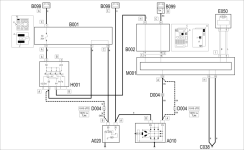
I used the E5010 Ignition and recharging wiring diagram. D004 connector and grey/black wire from D+ to plug A pin 25
Not how I read it

Pin 19 of connector A goes to D04

As per circuit diagram

And

Plug pin out

Might be missing something obvious

Petrol is colour W and diesel HN


1407BD1C-2D67-48BB-9680-0A7203715160.jpeg
 
When the alternator does not turn, and so does not recharge the battery, an earth signal is sent from pin D+ to the Body Computer M1 - pin 19 of connector A:
 
I think pin 19 is for the Punto diagram. Stilo might be different than Bravo 👍 The diagram I used is specific for Bravo
Yep my mistake for some reason when I come out of elearn I somehow forgot we were working on a Bravo and opened up stilo instead

When the alternator is not turning and therefore not recharging the battery, an earth signal is sent from pin D+ to the Body Computer M1 - pin 25 of connector A: the latter is connected via the CAN line to the instrument panel E50 and manages the switching on of the recharging warning light in the instrument panel and the display of any messages as described above.

Which i read as pin 25 is pulled to 0V with the ignition on and the engine not running which looks like a broken wire
 
Last edited:
That is correct - with ignition off I have 9.8v when measuring D+. When D004 is disconnected I have 9.8v on the wire from BCM and 0v on alternator D+ wire.

Not sure I follow - which wire could be broken ?
 
Aha,now I see. Are you thinking the grey/black wire is broken somewhere ? One of the first things I did was to measure the D+ wire from alternator plug and all the way in to BCM. The grey/black wire is not broken I'm afraid.

Could the BCM be broken or give out voltage when it shouldn't ?
 
No

The signal from the alternator isn’t reaching the BCM

Here mine

Key out 0V
Ignition on 1V
Running 13.5V

Back probing the the wire near the fusebox
C308B504-24D4-4192-A56A-C9BDAF99C0B5.jpeg
7CA32298-ECDE-4637-A16C-B0AC56EE35DE.jpeg
63FEC15C-A517-4066-A557-277E1B68FD01.jpeg
DDCEDEB5-B0B6-49EE-A0CB-FFFD51F01177.jpeg
 
I see what you mean. I will measure it again to be sure. Can't be careful enough when we have come this far. I am really hoping we are on to something as there could not be much else left.

I think you have gone out of your way helping me with this. For that I'm very grateful. I will measure first thing in the morning when it's light of day and I've had my coffee (y)
 
Do you know what/where the power supply for BCM is ? Is it a fuse ? Reading step 7 on this eLearn diagnose for "Battery warning light on" it says check Body Computer Node power supply and earth.
 
Do you know what/where the power supply for BCM is ? Is it a fuse ? Reading step 7 on this eLearn diagnose for "Battery warning light on" it says check Body Computer Node power supply and earth.
Yes it’s fused

If the dash lights come on as normal, door open, main beam, engine check and so on the the BCM is working fine.


At the moment you have a cable running from the alternator straight through to the BCM

Except when cranking the voltage along this grey and black wire is set via the alternator end

This should be close to 0V with the ignition on and the alternator not turning.

Ignore the connector we basically have a straight cable from D+ to the BCM what ever voltage is one side of the cable should be the same at the other

I would not be looking at anything else until this is fixed
 
Understood. So I will try to run a new wire all the way. Need to have the car on lift or jackstands so probably no time tomorrow.

I’ll report back as soon as I’ve done it.
 
Understood. So I will try to run a new wire all the way. Need to have the car on lift or jackstands so probably no time tomorrow.

I’ll report back as soon as I’ve done it.
No

I am say that you can’t test continuity within wires while still connected in a circuit as continuity may or may not be found through a different pathway

Measuring voltage can also be misleading unless the circuit is under load

And two ends of the same cable should be near enough the same voltage

I’d start by taking the D+ wire off the alternator. And measure the volts at the connection post. Both key out and ignition on. Both should be very low volts as there should be an internal drained to chassis ground.

If it’s above say 3V or above I would see if a jump lead from battery negative to the alternator case would lower it. If it didn’t I would suspect the alternator isn’t correct. While the D+ is disconnected I would measure the resistance to D04 if that was low ohms it time for a rethink.

We are working around a dash, body computer and ECU. All very expensive to replace. Especially the body as it need pre programming for the keys. Although we think we know the wires and colours there’s no guarantee the diagrams are correct.
 
I'll see what I can get done in a few days and it's cearly not as straight forward as I thought. I'm hoping it's the alternator but it may not be that simple. I have tried searching the subject but there is not much out there. Strange knowing the amount of Fiat's on the road through Europe. But I did find some info on a German forum regarding troubles after installing a non-OEM alternator - and in this case a Hella.

Google translated :
"After a long back and forth with the workshop that installed this Hella alternator at that time, I had the Hella removed again at the workshop and had an original Bosch reinstalled. And that was the cause of the peculiar error. According to workshop the Fiat definitely does not provide the required excitation current (and/or voltage) for the Hella. If you start the car it is not excited correctly, but gets excited even during the first few seconds. The residual polarity of the magnets is then sufficient to switch off the battery warning light during a direct restart, i.e. to indicate a correct excitation. The servo does not work, because without correct excitation of the Lima, the control unit switches off the largest consumers, and this probably includes the servo"
 
Back
Top