Usually relays are used to connect receivers which use higher current (headlights, motors, heaters) to spare switches and wires and money on them. A switch able to pass 30A for a long period of time will be bigger (uglier) and more expensive than one that that can pass 1A.
The signal is switched by the small switch, goes through the relay which powers the high current part of the circuit.
I don't know if the same logic is applied here, but I think it's not. Although could be similar.
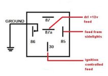
Normally (lights off and ignition on) the LEDs are lit up (the current flows to the LEDs), but when you switch on the dipped beam, the current is being cut off from the DRLs.
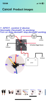
Check that on your diagram pins 87 and 87a are similar, but can serve 2 different devices. If you connect only one device, one of the two pins can be left empty.
In my diagram both DRLs were ment to be connected via same pin on same relay.
According to what NeilDD just wrote, the relay can be different. Hope the electrician checked what he got.
The signal is switched by the small switch, goes through the relay which powers the high current part of the circuit.
I don't know if the same logic is applied here, but I think it's not. Although could be similar.
Normally (lights off and ignition on) the LEDs are lit up (the current flows to the LEDs), but when you switch on the dipped beam, the current is being cut off from the DRLs.
Check that on your diagram pins 87 and 87a are similar, but can serve 2 different devices. If you connect only one device, one of the two pins can be left empty.
In my diagram both DRLs were ment to be connected via same pin on same relay.
According to what NeilDD just wrote, the relay can be different. Hope the electrician checked what he got.
")


 full job completed