Technical Change front end on 09 ducato x250 to 2015

Currently reading:
Technical Change front end on 09 ducato x250 to 2015

I'd rather use automotive connectors, but wago is good.

T-type (perhaps it's called differently in English, sorry) allows you to connect three wires together.

This type is crap, because it can cut the wire :(


So the link is just to show the idea.

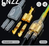
The ones on the attached screenshot are much better.

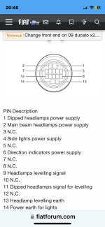
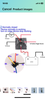
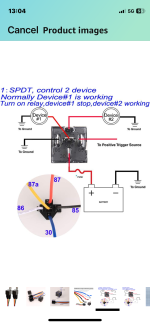
You need only one relay to connect both DRLs.

The connection I described above is my idea how I would do that, I have not tested it before, as I have the classical x250 headlights.

The description how to wire DRLs with the relay has been tested and works fine as requested by the EU regulations.

So first connect everything outside of the vehicle to test, but cut the wires and add connectors only after confirming that everything works fine. And disconnect the battery before you start :)
 

Attachments

  • Screenshot_20241004_001951.jpg
    Screenshot_20241004_001951.jpg
    362.1 KB · Views: 27
I would advise against using this type of Scotch Lock connector
NOT RECOMMENDED - https://www.ebay.co.uk/itm/175647979749?chn=ps&_ul=GB&mkevt=1&mkcid=28 NOT RECOMMENDED
I have used them in the past, generally quickest and easest to fit and they worked ok for a while, but then caused intermittent faults through bad connections - corrosion/whatever. It may be the wire was not the ideal diameter for them, but how are you going to check? I ended up having to remove them all and replace them with cheese block (screw down) connectors like these
RECOMMENDED https://www.screwfix.com/p/essentials-16a-12-terminal-strips-10-pack/91532 RECOMMENDED
Unfortunately the cheese block connectors are a lot more fiddly and time consuming to fit, but I have never had any bother with them so they saved time and prevented problems in the long run.
 
Last edited:
This post contains affiliate links which may earn a commission at no additional cost to you.
I would advise against using this type of Scotch Lock connector
NOT RECOMMENDED - https://www.ebay.co.uk/itm/175647979749?chn=ps&_ul=GB&mkevt=1&mkcid=28 NOT RECOMMENDED
I have used them in the past, generally quickest and easest to fit and they worked ok for a while, but then caused intermittent faults through bad connections - corrosion/whatever. It may be the wire was not the ideal diameter for them, but how are you going to check? I ended up having to remove them all and replace them with cheese block (screw down) connectors like these
RECOMMENDED https://www.screwfix.com/p/essentials-16a-12-terminal-strips-10-pack/91532 RECOMMENDED
Unfortunately the cheese block connectors are a lot more fiddly and time consuming to fit, but I have never had any bother with them so they saved time and prevented problems in the long run.
For the first link, I agree, that's why I wrote they are crap. It was clearly written that I post the link to show the idea of a T-type connector.

For the second link, I don't agree at all. They are good for households, were there are no vibrations, but in cars / vans the screws can become loose.

Automotive connectors should be used, in the engine bay I'd personally go for hermetic ones, as water and other fluids can bet under the hood.
 
This post contains affiliate links which may earn a commission at no additional cost to you.
For the first link, I agree, that's why I wrote they are crap. It was clearly written that I post the link to show the idea of a T-type connector.

For the second link, I don't agree at all. They are good for households, were there are no vibrations, but in cars / vans the screws can become loose.

Automotive connectors should be used, in the engine bay I'd personally go for hermetic ones, as water and other fluids can bet under the hood.
Cheese block connectors have worked ok for me - but my experience is limited and there may be a better way.
Certainly a quicker way which is more important for professionals to save time than it is for me.
I haven't seen the T type connectors - whats the difference in the way they make contact compared to a scotch lock connector?
I think the problems I had may have been caused by the conductor being too thin for the slit in the metal plate that is supposed to trap them tightly. I think they are only intended for a certain diameter of conductor. But how can you tell the diameter of the conductor in the existing wiring you are splicing in to? You don't even see it. And wouldn't you have the same problem with the T connector?
The thing about the cheese block connectors is they will grip tightly any diameter of conductor, unlike the plate with a fixed size gap that slides over them
 
Last edited:
For the first link, I agree, that's why I wrote they are crap. It was clearly written that I post the link to show the idea of a T-type connector.

For the second link, I don't agree at all. They are good for households, were there are no vibrations, but in cars / vans the screws can become loose.

Automotive connectors should be used, in the engine bay I'd personally go for hermetic ones, as water and other fluids can bet under the hood.
I agree too not great in a engine bay
 
I have just completed this convertion today what that video doesnt show is the fuse box also is in the wong place for the new head lights the bracket has to be cut and lowered .. the power steering & coolant bracket does mount up fine but leaves the ps hose to short also the water hose to short hope this helps
Happy have you got any input into the headlight wiring I’ve Inbox you few times
This is the last part has me clueless and any info will help the guy coming to wire
 
Well today didn’t go great at all he spent a few hours on it and had to leave he run out of time
he got all lights working but has a total of 3 wires left which are for auto levelling
He used x2 5 pin relays in total but no connections at all he soldered it all and heat shrink
Reason for relays so not running wires from other head light to one relay so used 2 and run a ignition feed from a wire he found in a harness
So I’m left with no levellers
But also another issues main beam kept going out on its own
Says he will call back Tuesday morning try sort the issues
 
I’m now starting to think every other person that’s done the facelift have no idea about the headlights to give any information because they didn’t sort it a auto electrician did
3 people now I have asked that have it and no feedback lol
Never mind find out the hard way 👍
 
I’m now starting to think every other person that’s done the facelift have no idea about the headlights to give any information because they didn’t sort it a auto electrician did
3 people now I have asked that have it and no feedback lol
Never mind find out the hard way 👍
That's quite possible :(
 
Well today didn’t go great at all he spent a few hours on it and had to leave he run out of time
he got all lights working but has a total of 3 wires left which are for auto levelling
He used x2 5 pin relays in total but no connections at all he soldered it all and heat shrink
Reason for relays so not running wires from other head light to one relay so used 2 and run a ignition feed from a wire he found in a harness
So I’m left with no levellers
But also another issues main beam kept going out on its own
Says he will call back Tuesday morning try sort the issues
I would assume the idea of the levelling is same in the x250 and x290. Have you looked together at the x250 levelling wiring diagram in post #97? There are 3 wires that go to the motor. And you have 3 wires left...

For the wiring colours, according to a non-factory service book (by Bucheli Verlags AG):

B - bianco - white
N - nero - black
R - rosso - red
M - marrone - brown
V - verde - green
A - azzurro - blue
H - grigio - grey
S - rosa - pink
G - giallo - yellow
C - arancione - orange
Z - viola - violet
L - blue brillante - light blue
W - noce scura - dark hazelnut (?)

If the diagram gives two letters (for example CA) it means the wire has two colours (orange-blue in the example).
Thanks mate this is actually what the auto should have done
I am not pulling the guy down because when he wired the lights going to each PIN number same has x250 in the wiring diagram it wasn’t the same
Reason indicator wasn’t working or high beam etc
So he had to basically just wire each at a time and then test one by one with a probe
Then had the issue of dlr are bright on key then then dim when ignition. So it did take a while
At first he did not listen to any feed back I got from you on the relay lol
He just wired his way
But had many wires left because drl was wired with no relay
He then changed that way and added drl to each relay
Once this was completed he tried and all lights worked including drl high beam and low etc but no levelling
But then … main beam went out
Was not blown bulb because came back on
But did it again and he say it’s the system doing it
It doesn’t like something
That’s when he had to go lol
Me personally think he had enough thrashed his head
I think it was a earth issue because these 3 wires still needed wiring in
I will try find the diagram have a look at this part myself
The hard part looks to be done
 
I would assume the idea of the levelling is same in the x250 and x290. Have you looked together at the x250 levelling wiring diagram in post #97? There are 3 wires that go to the motor. And you have 3 wires left...

For the wiring colours, according to a non-factory service book (by Bucheli Verlags AG):

B - bianco - white
N - nero - black
R - rosso - red
M - marrone - brown
V - verde - green
A - azzurro - blue
H - grigio - grey
S - rosa - pink
G - giallo - yellow
C - arancione - orange
Z - viola - violet
L - blue brillante - light blue
W - noce scura - dark hazelnut (?)

If the diagram gives two letters (for example CA) it means the wire has two colours (orange-blue in the example).
And yes sorry I did show him this diagram
He was reply was yes it’s for x250
On x290 plug which we have which each pin doesn’t something else reason in the beginning wasn’t working correctly
So he has 3 wires left
Black/grey grey and grey/blue I think!! Without looking at it
One of those is pin 9 headlamp levelling signal
Pin 11 Dipped headlight signal for levelling
Then 13 headlamp levelling earth
But again these are for x250 showing to these pins
His point on x290 plug has different colour wires and PIN numbers
 
I think the hard part is don’t
Surly it’s now a case of just trying each wire on probe with ignition to on
Once I know which one is earth it’s a case of sending power to the levelller
I did translate comment on polish guy video and someone had this part also
His reply was this which
I would assume the idea of the levelling is same in the x250 and x290. Have you looked together at the x250 levelling wiring diagram in post #97? There are 3 wires that go to the motor. And you have 3 wires left...

For the wiring colours, according to a non-factory service book (by Bucheli Verlags AG):

B - bianco - white
N - nero - black
R - rosso - red
M - marrone - brown
V - verde - green
A - azzurro - blue
H - grigio - grey
S - rosa - pink
G - giallo - yellow
C - arancione - orange
Z - viola - violet
L - blue brillante - light blue
W - noce scura - dark hazelnut (?)

If the diagram gives two letters (for example CA) it means the wire has two colours (orange-blue in the example).
also buddy even in the wiring diagram doesn’t give wiring colours does it only PIN numbers so again can’t really go on that
It’s either trying each wire until works or a proper tester because even a signal will show on a probe
So 1 wire earth 1 signal and 1 power that’s my understanding
I will get around this for sure and will post every detail of my finding
Thanks for helping tho 👍 I have never understood when some folk not all come to forums for help and find a way to sort it they never post findings
I will maksure information will be present for future fixes on this facelift
 

Attachments

  • IMG_8292.jpeg
    IMG_8292.jpeg
    166.3 KB · Views: 26
  • IMG_8330.png
    IMG_8330.png
    204.3 KB · Views: 22
has x250 in the wiring diagram it wasn’t the same

He was reply was yes it’s for x250
On x290 plug which we have which each pin doesn’t something else reason in the beginning wasn’t working correctly
His point on x290 plug has different colour wires and PIN numbers

Yes, they are different, everyone knows that. But having the x250 part spares you to do the reverse engineering on both sides. You only have to do it on the headlights side.

The problem is that x250 documentation is available everywhere, but the x290 isn't. FIAT and SEVEL are fu***rs, they changed the layout to make it more complicated. Although they could have left it as it was and just add the 2 extra wires for the DRLs. And the Polish guy on the video only comments on the headlight wiring was that the only difference are those 2 extra pins and that the plug from Croma can be used as it is cheaper.

Another problem is the SEVEL supplier of looms was playing around with wiring colours, they used what they had on stock, too :( Which adds more confusion.

I think that the documentation issue could be also caused by the fact that even FIAT is lost on the name coding :D x250, x251, x290 (which VIN starts with ZFA250...)

I'm happy to hear that the only thing left is the levelling :) Have you got pneumatic suspension on the rear?
I have air bag pump up buddy that’s all I know
My model is the comfortmatic
3.0 maxi 160 multijet very powerful motor it shifts for a 3.5 heavy loaded motorhome
 
So, if you have the airbags on the back suspension, you really don't need the levelling system in the headlights, you can always lower or higer the back of the camper ;)

But yes, do the job properly! till the end :)
lol 😂 yea it’s a mot instant fail in the uk apparently
Honestly tho I’ve never used the adjuster anyway
But still issue of main beam going out lights up goes out
Also 2 bulbs in total he blew for sidelights
So the computer doesn’t like something going on in the set up
Honestly I was not impressed with the auto he would not listen to me on information on the relay wiring to drl
If he did the first time he would have had time
Another mistake he wired soldered then tested 😩 I said no mate test before solder
But no … so he soldered all finished then nothing worked right
Then he listened to what you had say
Then he used relay for drl
Honestly was a bad day yesterday
But he was very cheap
Because did not complete job he gave discount too
Think he felt bad tbh
 
The x250 headlight wiring you put up showing PIN numbers on the rear of socket
Why is the headlight levellers not on this diagram
They are showing below numbers 9 12 and 13
But doesn’t show you this number on the pin diagram I find strange
But show you on the second image
 

Attachments

  • IMG_8380.png
    IMG_8380.png
    276.5 KB · Views: 35
  • IMG_8337.png
    IMG_8337.png
    172.4 KB · Views: 31
had a look today at how he’s wired the relay and noticed he’s used all the relay
So I’ve looked on Amazon at the relay I bought diagram which is this and again different to how you said
 

Attachments

  • IMG_8413.png
    IMG_8413.png
    902.7 KB · Views: 24
  • IMG_8416.png
    IMG_8416.png
    917.8 KB · Views: 22
Back
Top