Technical Temperature gauge 1991 Fiat

Currently reading:
Technical Temperature gauge 1991 Fiat

Rauti

New member
Joined
Apr 11, 2025
Messages
3
Points
1
Location
Hagfors
Hi everbody!

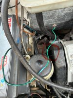
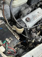
I have bought an citroen c25 mobilehome with a fiat turbodiesel engine.

My problem is that i cant get the enginetemperature to work on the dashboard.

The previous owner said that it worked last year.


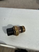
I have put a new sensor in but it doesnt work anyway.

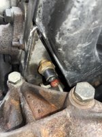
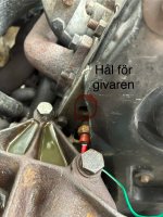
There are two sensor on this sitting aside eachother and im not sure witch one is for the watertemp. Is it the red one or the broken black one?

Does anyone know this?

Picture below.

Thank u!
 
Model
Citroen c25 fiat engine
Year
1991

Attachments

  • IMG_4929.jpeg
    IMG_4929.jpeg
    1.6 MB · Views: 11
  • IMG_4928.jpeg
    IMG_4928.jpeg
    834.5 KB · Views: 6
  • IMG_4943.jpeg
    IMG_4943.jpeg
    2.2 MB · Views: 6
  • IMG_4948.jpeg
    IMG_4948.jpeg
    4.8 MB · Views: 7
  • IMG_4949.jpeg
    IMG_4949.jpeg
    737.6 KB · Views: 7
Hi Rauti,

Welcome. I think that one sensor is for the temperature gauge, and the other is a thermostatic switch for the warning light. Later engines used a combined unit.

From advertisers data the sensor is M14 x 1.5, and the thermostatic switch is M14 x 1.25. Advertisements for the sensor show parts looking similar to your red device.

Does this fit with your observations?

As the thermostatic switch only connects the warning bulb to earth, it should be possible to read 12V to earth on your disconnected wire with ignition on. The cold bulb will have negligable effect when reading with a digital multimeter. I would expect a lower voltage on the gauge wire. A conclusive test may be to ground the wire for the warning light, but then you have to ground the wire while observing the light.

Thank u for your answers!

You think that the red sensor is for the temperature gauge and the black for warning light?

I did ground the wire (green one in picture) and the warning light came on. I can also read 12v from that same wire when the ignition is on.

This is not the wire for the temp gauge then?

Its the only wire i can find in that spot.
If when you grounded the green wire, the warning light illuminated, then that it is the wire for the switch.

Have you been able to measure the diameter of the thread on the black switch?

If the information that I have found is correct, then thread pitch should be 1.25mm, which is the same as that on a standard M8 bolt ( or use thread pitch gauges). If the sensor?? still in engine has 1.5mm pitch (same as M10 bolt) then assumptions are probably correct.

The sensor should be 1000 Ohms or less, while the switch should normally be open circuit.

Sorry but it seems that you have a missing wire.

I’ll measure the threads on the black switch tomorrow.

Do you have any information about the wiring for the temp gauge so i can make a new wire or how to easiest check were the cable broke or something like that?

Maybe i should install an aftermarket tempgauge?
 
I’ll measure the threads on the black switch tomorrow.

Do you have any information about the wiring for the temp gauge so i can make a new wire or how to easiest check were the cable broke or something like that?

Maybe i should install an aftermarket tempgauge?
I am sorry I have not found any wiring details for your model.

I owned 1990 Talbot Express (Peugeot J5) for many years, and while I managed to purchase an official workshop manual, it did not contain wiring diagrams.

On that vehicle, the instrument panel wiring was a flexible printed circuit, but I managed to identify the connection to the alternator (battery) warning light, and hence fit a D+ operated relay. Perhaps you could do the same with the temperature gauge connections?

Possibly a telecommunications style wire tracer could be used to find the route?

Repair would be much neater than adding an aftermarket gauge, wich would have to be mounted, as well as being wired .
 
Back
Top