Technical Rear suspension geometry

Currently reading:
Technical Rear suspension geometry

Joined
Jun 3, 2024
Messages
65
Points
69
Location
Cumbria
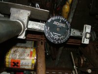
I’m playing with the suspension geometry and whilst the front makes sense I’m struggling to understand the terminology/numbers as referenced in the Fiat workshop manual. I’ve attached some pictures below which show what I’d like explained in simple terms if anyone can help?
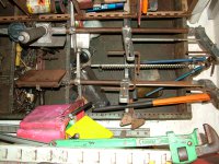
Also, the mountings for the rear arms that are held with three bolts, they are slotted and having been removed they are currently fitted just where they landed with no attention to the actual position, is there possibly a rule of thumb as to where I might start with them or is it just a case of adjusting them when dialling in the geometry?
As you might realise, I’m not much good at suspension geometry and related numbers so if possible it’s best kept to simplest terminology 😂
IMG_1134.jpeg
IMG_1135.jpeg
 
Others on Forum have more specific knowledge of this model, but looking at your diagram it appears that the tolerances for the rear wheels are from parallel, in other words inline with the car body line front to rear, to approx. a max of 25' (minutes) toe in, that is pointing towards the centre line of the car.
Obviously a suitable wheel alignment gauge is required to do this correctly and the optimum is the 10' (minutes) facing in towards the car centre line with both sides being the same position inwards.
The degrees and minutes are the measurements used on the alignment gauges.
As a basic starting point regarding the three mounting bracket bolts at B, you may on close inspection see the original marks where the washers sat when it was bolted up before dismantling.
Also I see the wheel at 90 degrees to the road, so what this means is that with the car on level ground the suspension must be loaded to a position that the wheels are vertical to the horizontal road thereby giving the 90 degrees.
 
Many thanks, that really helps as with the relevant search terms found what I needed to understand, thanks again for your guidance.

Pasted off google - “Angular measurements are commonly expressed in units of degrees, minutes, and seconds (DMS). 1 degree equals 60 minutes, and one minute equals 60 seconds”
On my old Dunlop wheel alignment gauge it then gives that in mm as well as degrees and minutes.:)
 
On my old Dunlop wheel alignment gauge it then gives that in mm as well as degrees and minutes.:)
If you can lay your hands on one, possibly from an old garage, the 'mechanical' (as against electronic) Dunlop gauges would be the ones to use. But when you measure from the rear (with the Dunlop gauges) you have to think backwards. The wheels have TOE-IN, so they are pointing slightly IN at their front, so if you site the gauges at the rear of the car, you need to read it as TOE-OUT. Due to their design, I don't think that you will be able to use the gauges at the front of the rear tyres (but happy to be proved wrong), but if you are able to, of course you are looking for 'toe-in'
 
Ah, I’ve been looking for a set of those but usually they are in poor condition or expensive.

The mm’s I’m presuming are over a given distance from wheel centre?
This is my set of Dunlop wheel alignment gauges at back of garage :)
I think from memory the mm or degree readings are the difference between the two points that the wheel alignment gauge touches the wheel rims.
You can probably read on the gauge first photo what the degrees equal in mm, note that varies on wheel diameter which has to be set on gauge when checking.
Re the ride height for checking you will notice how as you jack the car up or load it down the angle of the wheel alters in relation to the road.
The beauty of these gauges is if bent they can be zeroed before use, which you should do any way.;)
 

Attachments

  • DSCF1770.JPG
    DSCF1770.JPG
    466.7 KB · Views: 33
  • DSCF1769.JPG
    DSCF1769.JPG
    464.8 KB · Views: 34
This is my set of Dunlop wheel alignment gauges at back of garage :)
I think from memory the mm or degree readings are the difference between the two points that the wheel alignment gauge touches the wheel rims.
You can probably read on the gauge first photo what the degrees equal in mm, note that varies on wheel diameter which has to be set on gauge when checking.
Re the ride height for checking you will notice how as you jack the car up or load it down the angle of the wheel alters in relation to the road.
The beauty of these gauges is if bent they can be zeroed before use, which you should do any way.;)
When using the Dunlop gauges I was taught that first of all you align one of the pair with the wheels that you are aligning (to get the wheelsize and gauge in synchro), with one of the fingers up against its upright, than you put the gauges together and align the 2nd gauge with the 1st and 'zero it out', and only then do you lay the gauges up to the wheels.
 
When using the Dunlop gauges I was taught that first of all you align one of the pair with the wheels that you are aligning (to get the wheelsize and gauge in synchro), with one of the fingers up against its upright, than you put the gauges together and align the 2nd gauge with the 1st and 'zero it out', and only then do you lay the gauges up to the wheels.
yes , that's exactly what I was taught also.
We also had the Dunlop Caster/Camber and King Pin Inclination Gauges as well all in it's nice wooden box.
I notice these days on eBay they are selling the empty boxes for more than I have paid for the whole kit s/h in the past.:(
 
How essential is the ride height when measuring this?

The ride height is fairly important. Whilst cheap, light, simple and offering good ride comfort, the rear suspension design of the 500 does not have good geometry. The swing axle design obviously makes for large camber changes over its travel, but it also the toe changes quite a bit through the suspension travel.

My Haynes manual suggests you should be measuring toe with the car loaded with the weight of two adults in the front seats. Elsewhere on here I have read about measuring it with the suspension arms horizontal, but I can't confirm this.

Unladen my car reads a lot more toe out than the specification suggests.
To give you all a bit of a giggle, the wording in the Fiat FACTORY workshop manual reads as follows when adjusting toe-in and/or camber:-----the weight in the car should be---"Corresponding to an orderly load of 4 passengers"--note the word "ORDERLY". What I would like to know,does it matter if the load is a 'disorderly' load? On a more serious vein,I normally load the front compartment (by the fuel-tank) with some slabs and bricks when I am adjusting the toe-in and/or camber. Basically, you are trying to do the adjustments with the car in as similar position as can be as when you are driving 'the beast'. One thing to remember with regard to toe-in---when the final adjustment has been made, the track-rods must be as close the same length as possible---preferably the same. This is so that the "Ackerman Effect" is not adversly affected. According to 'The factory', toe-in should be between 0 and 2mm,-----I tend to set mine to as close to ZERO as I can.
 
I’ve scoured this forum on the subject of suspension geometry and don’t think I’m able to be 100% on a definitive method. I think I’m going to see just how many bags of sand it takes to get the car sitting as recommended in the Fiat manual, curious to know the answer! If it’s achievable without silly amounts of weight I think I’ll try to dial in the recommended spec and then see what it does when the weight is removed and then hopefully it’ll be apparent what might be suitable to set it at permanently. It might be a while before I get onto this as work is hectic and unless I take to my preferred mechanic who has the tools and patience already it is a little dependent on me sourcing a set of Dunlop tracking gauges, not as easy as it might be.
 
I’ve scoured this forum on the subject of suspension geometry and don’t think I’m able to be 100% on a definitive method. I think I’m going to see just how many bags of sand it takes to get the car sitting as recommended in the Fiat manual, curious to know the answer! If it’s achievable without silly amounts of weight I think I’ll try to dial in the recommended spec and then see what it does when the weight is removed and then hopefully it’ll be apparent what might be suitable to set it at permanently. It might be a while before I get onto this as work is hectic and unless I take to my preferred mechanic who has the tools and patience already it is a little dependent on me sourcing a set of Dunlop tracking gauges, not as easy as it might be.

Given the number of nut and bolt restorations seen carried out on the Fiat 500, both here and elsewhere on the internet, it is surprising that you have discovered a detail that nobody appears to have tackled. I suggest the best bet would be to contact one of the good specialist companies such as Motobambino or Proetti for advice.

I have the same manual as you and no doubt you have seen the specialised equipment that would have made this relatively easy for the factory and for workshops to set up when these cars were current. The rear arms on my car are original and in the original position, but the day will come when I need to tackle this. A replacement arm will not necessarily be aligned simply because the the brackets are fitted back in the footprint of the originals, and technically, the shim washers of the "estendeblocs" affect the setup and their locations are supposed to be decided by the use of a jig which will no longer be available.

In the manual there is a clue to how this might be done, although it would still requite a lot of time to set up, and a huge amount of patience. You would need a line drawn on a level floor and to devise a way (little plumb lines underneath?) to have the car placed perfectly centrally over that line. The manual tells you the height of the sump above the floor and the distance from the centre of a swinging arm to the underside of the floor that corresponds with the correct loading of the car to make the arms level. This being achieved, the correct toe-in of each wheel would be achieved when a line drawn from the centreline of a rear wheel veers inwards from being parallel with the car centreline by 5.5mm , measured at 1840mm from the centre of the rear wheel.
Unfortunately, the point at which this is measured is exactly underneath the corresponding front wheel.

This manual method of measuring the rear toe-in would be such a performance and so prone to inaccuracy that I will never attempt it. But if you give the workshop manual data to a decent garage that can do rear wheel alignment on a regular car, they should have sufficient comprehension of what is required to be able to tell you if their equipment is adaptible for this.

I think that this alignment is very important for enabling a Fiat 500 to give its safest and most pleasurable handling. Good luck however you achieve satisfaction on this. :)
 
Last edited:
I’ve scoured this forum on the subject of suspension geometry and don’t think I’m able to be 100% on a definitive method. I think I’m going to see just how many bags of sand it takes to get the car sitting as recommended in the Fiat manual, curious to know the answer! If it’s achievable without silly amounts of weight I think I’ll try to dial in the recommended spec and then see what it does when the weight is removed and then hopefully it’ll be apparent what might be suitable to set it at permanently. It might be a while before I get onto this as work is hectic and unless I take to my preferred mechanic who has the tools and patience already it is a little dependent on me sourcing a set of Dunlop tracking gauges, not as easy as it might be.
In your original diagrams it showed the rear wheels at 90 Degrees to the road when measuring with correct weight in vehicle.
So if you have a small spirit level that can span the wheel rim (not the tyre) at 12 and 6 oclock then when bubble in centre the wheel would be in correct measuring position with what ever load that takes.
Measuring without Dunlop or similar gauges will be difficult, the only way I could see it happening would be with a lot of chalk marking on the the floor and maybe a really straight and true piece of wood or metal held against front and rear wheels to mark and then lines drawn from there back past the rear wheels and lines measured at that point .
Of course taking in to account that "toe in" would be toe out" at the rear of vehicle as has been mentioned previously.
Re the Dunlop tracking gauges try looking for an old garage that has been trading for years, they may have an old set that gathering dust after buying an all singing Laser version and that could be bought or maybe "hired" for a few notes and a deposit.;)
Try a couple of bottles of wine as a bribe---works for me with my local garage (which is actually more a collection of cars and 'bits'). Sadly, the day of the 'local garage' where they worked on"anything and everything" is slowly becoming a thing of the past. Is there a "Classic Friendly" garage in your area? This was a system set up by Fuzz Townsend around garages that could (and, more importantly. were prepared too) work on "classic" cars.
 
Try a couple of bottles of wine as a bribe---works for me with my local garage (which is actually more a collection of cars and 'bits'). Sadly, the day of the 'local garage' where they worked on"anything and everything" is slowly becoming a thing of the past. Is there a "Classic Friendly" garage in your area? This was a system set up by Fuzz Townsend around garages that could (and, more importantly. were prepared too) work on "classic" cars.
Ha,ha! I used to repair friends computers on a system like that, although made sure the first part of the evening was for the repair and the second part was the imbibing.
I did specify Italian red of course.;)
 
... it is a little dependent on me sourcing a set of Dunlop tracking gauges, not as easy as it might be.

It's quite possible to do tracking without a tracking gauge, its just a bit of a faff. I've been using the 'string' method for around a decade now and have taken cars I've tracked at home to an alignment shop and found them to be within tolerance. The idea is to set-up a pair of parallel strings each side of the car and then you can measure the track from there.

To start with you need to know the track widths of the car, in the case of the 500 thats 1,118mm front and 1,130mm rear. This means the rear is 12mm wider than the front, thats 6mm each side.

Then you need 4 axel stands (or other similar height, fairly heavy objects) and some strong thread (I've been using some heavy weight cotton thread I bought to do the stitching on my Daimler interior). Position the axel stands at each corner of the car and then tie a length of thread at the height of the centre of the wheel on each side. So you have a string running along each side of the body.

Now to get the strings parallel, knowing our track width tweak the axel stands till the strings sit 6mm closer to the centre of the rear wheel than the front. You can use any measurement, but I normally start with 100mm for easy maths! So I'll use a rule to measure from the string to the centre of the front hub, and move the front axel stand (keeping the thread taught) till the thread is 100mm from the centre of the wheel. Then at the back I want it to be 94mm (6mm less due to track width), so I move the rear axle stand till it measures 94mm. You have to go round the car 2-3 times till the numbers stay consistent, as moving the rear axle stand will effect the front measurement a little and vice versa.

That's the awkward bit over, now you can simply use the rule to measure the distance from the front and rear edges of the wheel rim to the string. If the measurement is bigger at the front of the rim, the wheel is toe in. If the measurement is bigger at the back of the rim then it's toe out.
 

Attachments

  • IMG_1866.jpeg
    IMG_1866.jpeg
    189.8 KB · Views: 26
Back
Top