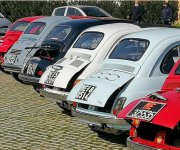
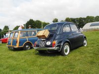
I've seen this (dark car 3rd left) or similar split i.e. 2 piece rear engine cover in a few photos. It appears to be a bottom section hinged as per normal and a top section hinged at the top. Intriguing! Does anyone have any more details about what it is and if it's a commercial part or DIY?


You are using an out of date browser. It may not display this or other websites correctly.
You should upgrade or use an alternative browser.
You should upgrade or use an alternative browser.
General Split engine cover
- Thread starter Noah500
- Start date
Currently reading:
General Split engine cover
Bigvtwin996
Established member
- Joined
- Jul 19, 2011
- Messages
- 1,393
- Points
- 445
I would say probably DIY from 2 covers.... cut so you could bend a flange over each peice to provide some strength and prob look factory rather than some dodgy spot welded strengthener...
I was thinking that... for a single cover it would have to be cut carefully and a flange welded on each part... though it might be difficult to get the curve right on both.
Bigvtwin996
Established member
- Joined
- Jul 19, 2011
- Messages
- 1,393
- Points
- 445
if you allowed 10mm on each edge you could (if good( cut slits and bend that edge over a former and tig the joins...
or you could Joggle a peice and as you say weld a flange on...
I thin the slit and ben would look best from a critical poin of view
or you could Joggle a peice and as you say weld a flange on...
I thin the slit and ben would look best from a critical poin of view
the hobbler
Distinguished member
- Joined
- Jul 25, 2012
- Messages
- 4,337
- Points
- 1,088
If would suggest that if you tried to make the 'split'cover from just one engine cover and wanted them to close closely and neatly in the middle, you will have a very difficult job to achieve that AND retain some amount of stiffness in each half. I think that the only way to do it properly would be to make it from 2 engine covers and be very precise with your cutting of them; at the bottom on th top half and the top of the bottom half. When you cut the covers into their 'halves' you will have to cut them so that, prior to folding them at the meeting point of the two halves, you still have the metal left on them for the overlap of what you want to use as the strengthening flange/fold-over.if you allowed 10mm on each edge you could (if good( cut slits and bend that edge over a former and tig the joins...
or you could Joggle a peice and as you say weld a flange on...
I thin the slit and ben would look best from a critical poin of view
Bigvtwin996
Established member
- Joined
- Jul 19, 2011
- Messages
- 1,393
- Points
- 445
thinking... if you had 2 covers and made the first half....
then it may make it easier to measure up the other half.....
rather than make 2 cuts and hope they line up....
you could even be very clever and the lower half have an extra lip for a seal or such so the top half lower edge has something to close up against..
Forgive my crude artwork

then it may make it easier to measure up the other half.....
rather than make 2 cuts and hope they line up....
you could even be very clever and the lower half have an extra lip for a seal or such so the top half lower edge has something to close up against..
Forgive my crude artwork
Bigvtwin996
Established member
- Joined
- Jul 19, 2011
- Messages
- 1,393
- Points
- 445
spoke with a mate (fabricator) about this... he has a totally different view....
Draw a line where you want the join...
now the next part is down to skill... make a template of the curvature of the panel along the line...
he said at his place they have one of those things that you use to mark fancy shapes for cuting tiles but its about 2m long
they would then cut that profile twice once for the bottom once for the top edges...
then shape it for the upper panel... and the lower, but the lower makigng sure the lip allowed for a seal to be applied...
the shapes being a sort of L
the lower lip longer so that there is space for the seal...
he said they would gut the line with a 2-3 mm disk thus allowing a small gap....
and weld the lips on to the panel edges
like this...

it should be welded at the ends to the sides of the panel and he would add some triangular strengtherners between the lips and the panels
if tig welded on the inside it should be possible to grind the edges round so it looks like it was pressed...
Draw a line where you want the join...
now the next part is down to skill... make a template of the curvature of the panel along the line...
he said at his place they have one of those things that you use to mark fancy shapes for cuting tiles but its about 2m long
they would then cut that profile twice once for the bottom once for the top edges...
then shape it for the upper panel... and the lower, but the lower makigng sure the lip allowed for a seal to be applied...
the shapes being a sort of L
the lower lip longer so that there is space for the seal...
he said they would gut the line with a 2-3 mm disk thus allowing a small gap....
and weld the lips on to the panel edges
like this...
it should be welded at the ends to the sides of the panel and he would add some triangular strengtherners between the lips and the panels
if tig welded on the inside it should be possible to grind the edges round so it looks like it was pressed...
I found a picture of another one
 ... looks really neat!
Spoiler alert - around New Year I took possession of two old engine covers... work underway to give this a try. More to follow ")
....you're going to makea spoiler?
...actually, I suppose it will be somewhat like a spoiler....you're going to makea spoiler?
It's now Feb. 6, what's keeping you?Spoiler alert - around New Year I took possession of two old engine covers... work underway to give this a try. More to follow
Aw, don't spoil it.....you're going to makea spoiler?
the hobbler
Distinguished member
- Joined
- Jul 25, 2012
- Messages
- 4,337
- Points
- 1,088
In case you didn't know, let me tell you the real reason why the small Fiat 600 based Abarths had their engine cover fully raised. Contrary to what most people assume, it was NOT to assist engine cooling (although in hindsight, it did help). In (I believe) the mid 1960s one of Abarth's top test drivers, Mario Poltronieri, was conducting a track test on one of the 600 based racers (probably a 1000tc) when he realised that the more the engine-cover was lifted , the faster the car went---until with it opened to horizontal, it added 5mph (8kph) to the top speed; it WAS an early boot-spoiler! Eventually everybody did it with their small Abarth racing saloons so it didn't gain them a great deal. When you think how much development (expense and time-wise) would have to be spent to make the engine alone make the car go that mush faster, the cost of 6 pieces of tubing, 8 pieces of small angle-iron and about 2 hours of welding turned out to be a real result. I have the engine-cover 'lifted' on my replica '695' Abarth----I would be comfortably off if I got a fiver for every time I was (incorrectly!) TOLD as to the reason that the engine cover was on struts. But I will concede that whether it makes any difference to the top speed of MY car IS open to debate!...actually, I suppose it will be somewhat like a spoiler
Yes, I knew that
Not sure how much downforce will be generated with a standard 499cc engine, though. I'm doing it more for the fun of having a little project than for any potential aerodynamic or performance benefits. I'm still keeping the original untouched lid and the way I have mounted the hinges on the air vent panel means I can go back and forward between the lids without have visible extra holes, etc.
Not sure how much downforce will be generated with a standard 499cc engine, though. I'm doing it more for the fun of having a little project than for any potential aerodynamic or performance benefits. I'm still keeping the original untouched lid and the way I have mounted the hinges on the air vent panel means I can go back and forward between the lids without have visible extra holes, etc.
I sometimes drove my Fiat 127 hatchback with the hatch open supported by the gas struts (e.g. when carrying long items). I noticed as the speed increased, the more the hatch was being pushed down, so it must have been trying to provide some downforce. I can't say if it increased my top speed, but I can confirm that the faster I went, the more exhaust fumes entered the cabin. (cough, cough ).
).the hobbler
Distinguished member
- Joined
- Jul 25, 2012
- Messages
- 4,337
- Points
- 1,088
The hinges to use when moving the pivot point of the engine cover from the bottom to the top are small chrome hinges. One source is "Axel Gerstle"--part number:---23485 (E85). The top of the hinge is mounted at the very bottom of the vent-panel that sits under the rear window, and the engine-cover part has to be carefully located so that you can fully open the engine cover without marking the body work under the vent-panel---best if you have a 2nd pair of hands to help position everything. It can be a bit of a faff to alighn all the 4 parts. I made up little gaskets to sit between the hinge parts and the body-work.I sometimes drove my Fiat 127 hatchback with the hatch open supported by the gas struts (e.g. when carrying long items). I noticed as the speed increased, the more the hatch was being pushed down, so it must have been trying to provide some downforce. I can't say if it increased my top speed, but I can confirm that the faster I went, the more exhaust fumes entered the cabin. (cough, cough
Part of the reason that by lifting the engine-cover to the horizontal the vehicle's speed is increased, is that you reduce the 'suck' area at the rear of the car---the edge of the engine-cover helps deflect the draught away from the complete rear of the car. As I said, whether it increase the top peed of my car is open to debate---but it definitely worked for the Fiat 600 based racers.
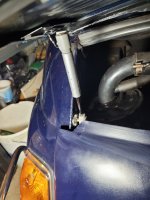
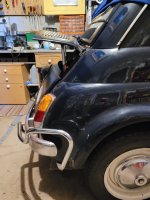
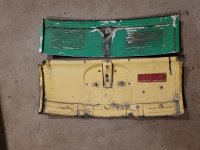
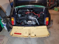
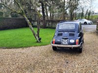
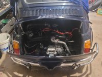
So, following my earlier posts I've now complete my construction of a split engine lid/over/bonnet. My objective was to get the look of the ones that I had seen, with the top section opening up for added stability/aerodynamic/down force/visual impact but minimising the difference from a standard lid when closed. I'm keeping the standard lid as it is the original and I may want to switch back at some point.
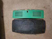
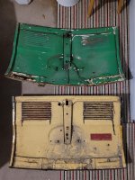
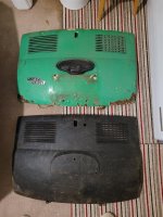
I started with 2 secondhand lids from eBay, both of which had flaws on either the top half or the bottom half - no problem since I wanted the top of one and the bottom of the other with a bit of an overlap to avoid having a gap in the middle. One of them came with a number plate light holder, badge and stay fixing.
It's taken a while to do as it needed quite a lot of thinking about how to achieve it, then time to order parts, etc. and some trial and error.
Top panel
but minimising the difference from a standard lid when closed. I'm keeping the standard lid as it is the original and I may want to switch back at some point.I started with 2 secondhand lids from eBay, both of which had flaws on either the top half or the bottom half - no problem since I wanted the top of one and the bottom of the other with a bit of an overlap to avoid having a gap in the middle. One of them came with a number plate light holder, badge and stay fixing.
It's taken a while to do as it needed quite a lot of thinking about how to achieve it, then time to order parts, etc. and some trial and error.
Top panel
- cut in two at the fold on the bottom of the vent panel and rusty bottom part discarded
- complete removal of the central reinforcing strip on the back, since I didn't need the lock any more
- trim back of some of the return edge on the top lip, to allow for clearance when folding up
- lock hole filled with a bit of steel (from the scrap part of a panel) with the edges pinched over to fit on the back if the hole, fixed in place with Araldite... hopefully it will stay in place
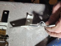
- extra tabs made from more sheet cut from the unused part of the panel on which to mount the gas struts
- holes drilled to take bolts for the hinges and nuts Araldited in place between the back of the panel and the top reinforcement strip on the back
- inside painted gloss back (saving over body colour paint )
- outside rubbed down, filled, primed, painted in body colour and lacquered
- foam tape fixed to the back of the bottom of the lid to stop rattling if driven with the lid closed
- no handle/knob, just lift up at sides
- no catches fitted as gas struts seem to hold the panel shut
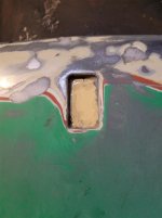
- lock recess filled with a Union Jack enamel badge which I happened to have and fits
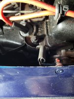
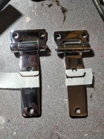
- stainless steel hinges from eBay (as the 'correct' ones were somewhat pricey) and cut them down.to be smaller
- gaskets made from bicycle inner tube stuck in the back
- fixed to the return lip of the bottom of the air vent panel above engine bay, to minimise visual impact and make it easy to switch back to my standard lid if needs be
- hinges and bolt heads painted body colour to minimise visual impact
- the shortest I could find, designed for top-lifting kitchen cabinet doors
- mounts fitted to the inside edge of the engine bay and the tabs on the top lid
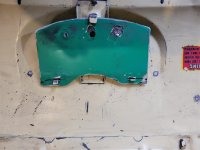
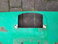
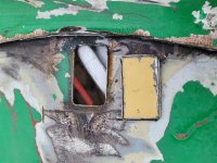
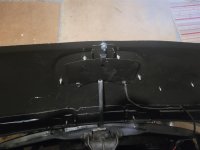
- cut in two about 2.5cm up from the fold below the vent panel. and top part discarded
- sides of the overlap part of the bottom lid slit in and folded from the edge so there would be minimal interference when the bottom of the top lid sits on it. These were
- central reinforcing strip cut down and bolted to the lip with a spacer to maintain previous gap
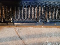
- number plate light holder heat shield made from a piece of steel cut out from the other bottom lid
- paint as per top panel
- I wanted to avoid external fixings such as rubber catches or bonnet pins, so I fixed stainless steel bolts on the inside edges of the engine bay and drilled holes in the folded over side tabs so they could be pulled on to (hopefully) stay in place. If it doesn't work out I may look at something else e.g. Dzus fasteners
- Extra rubber bumpers fitted to the edges of the engine bay to support the edges of the bottom lid. These were aftermarket and appear to be made of some sort of plastic rather than rubber so I had to cut down the cones to be able to pull them through the holes I drilled.
- light plate dismantled, cleaned and painted with gloss black
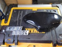
- Fiat 500L badge repainted with black enamel, new star clips to hold it on
- change the method of fixing the bottom panel shut
- fit something to hold the top panel shut (Dzus fasteners? magnetic foam tap?)
- move gas strut mounting points lower to make open lid a bit more horizontal
- fit a stay to hold the top panel open if it gets pushed down by airflow when open
- replace the Union Jack badge with something more Italian - either to fit the recess (c. 42x21mm, if anyone has anything suitable they want to part with?...) or to stick over the top
Attachments
-
 2024-08-18 18 Milestones Museum, Basingstoke (Large).JPG334.6 KB · Views: 22
 -
 2025-01-29 01 Engine lid (Large).jpg253.6 KB · Views: 21
 -
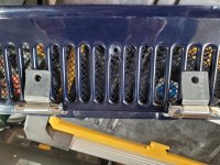
 2025-01-08 02 Engine lids (Large).jpg211.5 KB · Views: 16
 -
 2025-01-08 01 Engine lids (Large).jpg284.7 KB · Views: 17
 -
 2025-01-29 02 Engine lid (Large).jpg297.1 KB · Views: 16
 -
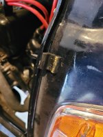
 2025-01-30 03 Engine lid hinges (Large).jpg401 KB · Views: 15
 -
 2025-01-30 04 Engine lid hinges (Large).jpg298.2 KB · Views: 16
 -
 2025-01-31 06 Engine lid hinges (Large).jpg333 KB · Views: 16
 -
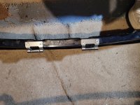 2025-01-31 07 Engine lid hinges (Large).jpg396.7 KB · Views: 16
 -
 2025-02-04 03 Engine lid heat shield (Large).jpg198.1 KB · Views: 17
 -
 2025-02-04 02 Engine lid heat shield (Large).jpg388.7 KB · Views: 15
 -
 2025-02-04 01 Number plate light and badge refurbished (Large).jpg309.9 KB · Views: 16
 -
 2025-02-01 01 Engine lid bumper (Large).jpg191.4 KB · Views: 15
 -
 2025-02-04 04 Engine lid hinge gaskets (Large).jpg349.9 KB · Views: 16
 -
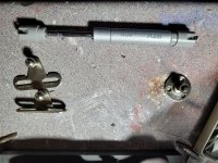 2025-02-07 02 Engine lid strut (Large).jpg400.6 KB · Views: 16
 -
 2025-02-09 02 Engine lid (Large).jpg267.8 KB · Views: 16
 -
 2025-02-09 04 Engine lid (Large).jpg290.7 KB · Views: 15
 -
 2025-02-11 01 Engine lid lock hole filled (Large).jpg302.1 KB · Views: 20
 -
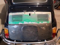
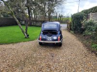 2025-02-21 02 Fiat 500 (Large).jpg578.4 KB · Views: 22
 -
 2025-02-21 01 Fiat 500 (Large).jpg571.3 KB · Views: 22
 -
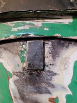 2025-02-11 03 Engine lid lock hole filled (Large).jpg167.9 KB · Views: 21
 -
 2025-02-11 02 Engine lid lock hole filled (Large).jpg101.2 KB · Views: 20
 -
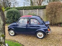 2025-02-21 03 Fiat 500 (Large).jpg582.9 KB · Views: 21
 -
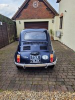 2025-02-21 04 Fiat 500 (Large).jpg497 KB · Views: 21
 -
 2025-02-21 05 Fiat 500 (Large).jpg269.6 KB · Views: 22
 -
 2025-02-21 06 Fiat 500 (Large).jpg125 KB · Views: 23
Last edited:
A couple of slight tweaks:
- spring fitted to the centre of the bottom lid to hold it in place - it hooks onto the engine lifting ring
- side tabs of the bottom lid cut off and bolts removed to make it easier to open and close, and to leave space for...
- the gas struts to be moved lower and get the open top lid more like horizontal when open instead of tilting up