MAP/Barometric Pressure - What does that mean?

Currently reading:
MAP/Barometric Pressure - What does that mean?

Joined
Aug 8, 2006
Messages
3,884
Points
707
Location
Ayr, Scotland
Danger Volvo Related :p

Posted the following on the volvo forum but not expecting a flurry of reply so thought i'd post here too as its not really specific to one car or another.

--------

Ok so after replacing my rear lambda sensor which had been showing an error, and was covered in soot. The car ran fine, however 2 days later the engine managment light came on again, this time i could get the OBD reader working and it read:

P0107 - MAP/Barometric Pressure Circuit Low Input

I cleared the code to check it wasnt a 1 time thing and it came on the following day with the same code.

The car is a:

Volvo S40 2.0 Turbo 2002

But am unsure of what the code actually means is happening. I understand that its something to do with manafold pressure, but is this the turbo or the exhaust and how do i fix check it?

Did a full service with new plugs, oil, air and fuel filters at the same time as changing the rear oxygen (lambda) sensor.

Cheers. (y)
 
the map sensor monitors pressure in the inlet manifold, and in a turbo car it will report levels of boost. it is critical that it is working correctly.

also, the rear lambda sensor shouldnt have any real impact on how the car runs. the ECU will use the pre-cat lambda for fueling, and second lambda is just to check that the cat is working correctly.
 
Ok so have an autodata cd i didnt know i had, so got some more info:

The error code and the possible causes
volvo error code.jpg

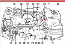
Location of barometric sensor.
volvo engine layout.jpg

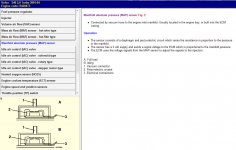
DOnt know location of MAP or how to test clean Barometric sensor, or how to test the MAP when i find its location.

volvo MAP.jpg

Any help anyone?
 
Number 20 highlight on your engine pic leads to the MAF (Mass air flow meter)

As Arc stated, the MAP monitors Manifold Air Pressure. Barometric sensor is another name for MAP sensor. IE When you want to know air pressure you use what weather men use, a Barometer.

You need to find out what the resistence range is for the sensor is and measure with a multimeter.(set to ohms)

The sensor should be attached to the inlet manifold. It could be anywhere.
 
Yup yea knew no 20 was the MAF, similar config to the Bravo etc. I'll have a look around the Barometric sensor, and see where it leads to and see if anything has been disturbed and clean up any connectors etc. The volvo community arent the most helpfull bunch and take ages to answer stuff.. guess they dont have as many problems... lol.

I have a copy of VADIS ;) so i'll install that and have a look through any info on it now i have an idea of what i'm looking for.

Thanks (y)
 
according to your fault code you have a short to earth on the map circuit. you need to find the short. this could be an internal sensor or ecu fault but that is less likely than a wiring fault for this code.

according to the final attachment, on your car the map is built into the ecu casing or located in the engine bay. the best way to find it is to follow the vacuum hose from the inlet manifold.

i would identify the ecu connector pins used in the map circuit (haynes wiring diagram) and sensor connector (disconnect sensor) to do some continuity to earth tests with the circuit isolated. basically check if it is still earthed once isolated. it should not be, if it is you need to find the short (damaged wire). if it isnt earthed when isolated then the fault is in the sensor or ecu. you could then test the sensor seperately using a multimeter. since we dont know what values to expect, and we dont have a sensor map, this will require a small amount of detective work.
 
Last edited:
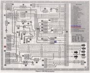
Ok well giving the contact a good clean with electrical contact cleaner didnt help much. Codes were off for about 8 miles then came back. I cant find the MAP on the Haynes wiring diag to trace it back to test it:

Volvo Diag small.jpg


Have got a higher resolution scan if needed.
 
there's definately no MAP on that diagram.
are you 100% sure its the correct diagram?
if it is then i guess we need to assume your MAP is the MAF (46) on that diag :confused:

first do continuity tests to find any broken wires
do continuity test between ecu connector pin 16 and map connector pin 2 (green/black wire)
do continuity test between ecu connector pin 15 and map connector pin 1 (green/grey wire)
do continuity test between chassis earth and map connector pin 3 (red wire)

we expect to see continuity on all 3. a broken wire would explain a failed test.

now test for short to earth probs on the 2 signal wires (keep both ecu and map connectors disconnected during all tests)
do continuity test between ecu connector pin 16 and chassis
do continuity test between ecu connector pin 15 and chassis

we do not expect to see continuity in either test. if you do it means the wire is earthing somewhere (damaged wire insulation sheath)

now test the ecu (dont be afraid, this is a very safe test method)
connect the ecu's connector
disconnect the map connector
switch on ignition
measure voltage across map connector pins 1 & 2 (set multimeter to dcV)
we expect to see 3vDC or 5vDC. not sure about the volvo since i have little first hand experience with them at this level, but it will almost certainly be 3 or 5 v.
if you dont have a constant 3v or 5v signal it would suggest the ecu is the problem. (let me know what you get either way)

now test the map (assuming it is same setup as other MAP's i've tested, pretty safe bet tbh)
what we want to do here is measure the output voltage from the sensor with engine running, at 2 different stages- idle and wide open throttle.

assuming the MAP is a 5v ref signal (most common) we can also assume at idle the signal voltage should be approx 1v, and at wide open throttle the signal voltage should be approx 3v+.

obviously to measure these 2 stages we need to have the MAP fixed in position, the car running, and the ecu connected to the MAP to send the reference voltage. so basically you need to put everything back together and have the engine running.

to measure the voltage you will need to access the green/black wire with one multimeter ternimal and the green/grey wire with the other terminal. to do this i would stick a piece of wire into the MAP connector pin 2 and another pice of wire in MAP connector pin 1. you can then connect the MAP jamming these bits of wire in position. you can then use these 2 pieces of wire to touch the multimeter terminals, giving you a constant reading (almost a DIY oscilloscope approach :D )

ok so you've set that up and you now have the engine running at idle and the multimeter shows a voltage, hopefully 1v. now fully open the throttle. you should see the voltage rise quickly up to 3v+.

if you started at 5v at idle it means either the vacuum hose is blocked or leaking badly, or the MAP has lost its vacuum reference (need new MAP in that case).


without having a manual for reference, or experience with this car, i'm assuming the most common set up for everything. variations happen and could impact what we expect to see in the tests, so let me know if anything is not as i've assumed.
 
Last edited:
Ok so gave up halfway through the testing, wasnt sure what i was doing really, so booked it in last week to my local volvo independant specialists and it went in today, and a few hrs latter got the results, its the MAF thats causing the error, the guy said the part costs £280+vat from volvo, he can get it for £220+vat, but told me that i'd be better off getting it off the web as i should be able to pick it up much cheaper and fit it myself. Really nice guy and he was the garage owner, nice to find someone honest.

I just need to find a MAF for the S40 2.0T 2003 now, the guy at the garage said he was sure the were interchangeable accross the range, but it seems they carry different part numbers for some of the models, am gona have to check with the Volvo forums etc to see if thats the case. They certainly look identical and look to have all the same fitting points and plugs etc.

Anyone reccomend any good MAF suppliers, online or otherwise.
 
so the diagram was correct and you did have a MAF rather than a MAP. :rolleyes:

try ringing every scrapyard and breakers within 100 miles. there cant be many 2.0T's sat around in the mud, its the kind of car that would be fixed up or broken into "off the shelf" parts. a specialist volvo breaker is probably your best bet, but i dont know where one is.
 
Back
Top