

Technical How to make a OCS sensor
- Thread starter gsc1ugs
- Start date
Currently reading:
Technical How to make a OCS sensor
i highly doubt that a single diode and resistor will replicate what the airbag ecu needs to see....id forget that design for a start. either consider making one of the more complex ones or buy the emulator from ebay
According to Fiat: "The front passenger air bag is equipped with a sensor, located inside the passenger seat between the padding and the external cover of the seat, able to recognize the presence of the occupant and classify his/her weight. This allows ensuring the best protection under any circumstance, modulating the inflation pressure of the front passenger air bag as a function of the occupant weight.
If an adult sits on the front passenger seat, the relevant front air bag is ready to intervene in case of need. If the passenger seat is free, the air bag will not intervene.
slightly confused why you posted that TT, but im probably missing something...
slightly confused why you posted that TT, but im probably missing something...
Same here.

We all know what the OCS is supposed to do. The thread is about making an emulator to avoid buying a new OCS. (Not something that I condone, but each to their own).
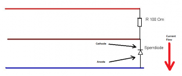
this is a silly conversation, im going to be bold and say that circuit is a pile of S***, what would be the point of isolating the ground with a diode? and if it was the other way aroud you just have a very crude and crappy voltage divider, anyone reading this, dont make this circuit, its far to simple to do anything useful, your more likely to get an airbag go off in your face than cure an airbag warning...
Why would the resistor have to flow thru diode to common? That doesnt make sense, surely the diode is there to stop flow to common?
Thats something you should be asking the person who created the circuit and supplied the diagram.
https://www.fiatforum.com/members/stec
I'm just informing you that you I think you have the diode the wrong way round if your trying to replicate stec's circuit. It may also be the reason it failed to work when you first tried. I'm not saying it does work, just that for it to have a chance of working you atleast have to follow his diagram.
Last edited:
i work in a radio engineering workshop, have a degree in telecoms and electrical engineering (in progress) and am a member of the IET....i'd say i'm "qualified" to answer your question...which ever way round you have a diode, it is pointless to have the "+" end presented normally with 0v, in this instance you might aswel have no connection as the diode is going to block any useful current trying to get to ground....ive said it before, this circuit will do nothing...throw it away and condemn it, even the OP didn't know if it worked, and no-one ever confirmed it working


without a shadow of a doubt (just tested it with a multimeter at work to be sure) A
without a shadow of a doubt (just tested it with a multimeter at work to be sure) A
Damn, not sure why but I though electrons flowed from Negative to Positive.
they do! its just everything in the world is currently labled backwards and will continue to be its called "conventional current" just be a sheep and forget you know it and everything still makes sense...

i know the feeling lol

according to the original diagram, yes its the wrong way round...i suppose its pointless to tell you again, this isnt going to work, and to stop worrying about the orientation of a diode in such a silly circuit.....
Only the designer, manufacturer or someone who's bought one and opened it would know that.
Possibly the circuit shown in posts 8 or 9 above. ???
Possibly the circuit shown in posts 8 or 9 above. ???