Technical Guess what... X244 2005 Motorhome Dipped Not working (still had full beam, indicators etc)

Currently reading:
Technical Guess what... X244 2005 Motorhome Dipped Not working (still had full beam, indicators etc)

ClubmanGT

New member
Joined
Jun 24, 2024
Messages
13
Points
3
Location
West Sussex
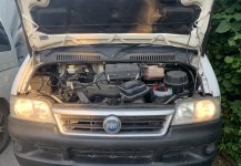
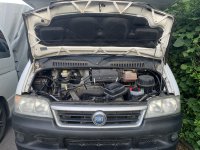
Hi all,

Sorry I know this has been discussed to death and even this recent post https://www.fiatforum.com/threads/no-dipped-beam-height-adjuster-buzzing-2003-ducato-2-8-motorhome-base.509374/ didn't resolve the issue.

The fuse mentioned in this post has been upgraded to 15A and is OK.

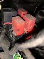
Also mentioned on that post in the Relay box in the engine bay... Mine has the issue of wiggling it and the side lights will go out one side etc. So annoying.

However trying pretty much everything I can see online I still have no dipped beam.
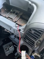
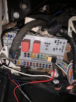
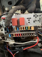
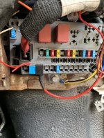
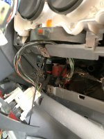
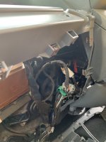
The cab is an absolute mess right now as I have tried to find anything else (mouse chewed etc)

The van was recently purchased I will add.

Thanks in advance.

Sam
 
Model
2005 2.8JTD x244
Year
2005
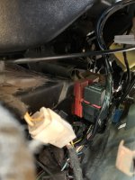
IMG_3144.jpeg
IMG_3143.jpeg
IMG_3142.jpeg
 
From the scale of the destruction it must have been a super mouse! Lucky that it wasn't a pine marten, which I believespecies are a major threat to vehicle wiring in Germany.

Have you downloaded my annoted copy of eLearn diagram E2011 from the other thread to which you linked? Perhaps you already have a Fiat wiring colour code translation chart, but I will attach mine which is designed for A5 printout.

Are you able to connect the battery for testing? If yes than we can proceed. You have probably done most of the following.

1. Remove relay T02 and apply temporary short between terminals 30 and 87. Dipped beams should illuminate. If OK replace relay.
2. I see that you have access to the switch control panel. Identify connector "A", and unplug. Identify pole A8 (Light Blue/Green).
3. With battery connected, and ignition on, apply temporary earth to pole A8 of the harness cinnector. Dipped beam should illuminate. Replace connector A on H090.
4. With ignition and sidelights on, apply temporary earth to connector B4. Again dipped beams should illuminate.

You should now have a clue as to where the problem is.

I cannot currently understand why jiggling the Engine Bay Fusebox (B001) should affect the sidelights on only one side. The split is in the LH Cab Fusebox (B002). I am concerned that the supply to the ignition switch via fuse F3 (30A) is being interrupted.
 

Attachments

  • Fusebox B001 Engine Bay.pdf
    191.2 KB · Views: 52
  • Fusebox B001 Engine Bay.pdf
    191.2 KB · Views: 55
  • Fiat Wiring Colour Codes.pdf
    70.1 KB · Views: 58
  • eLearn E2010 Side & Rear Lights.pdf
    88.1 KB · Views: 39
From the scale of the destruction it must have been a super mouse! Lucky that it wasn't a pine marten, which I believespecies are a major threat to vehicle wiring in Germany.

Have you downloaded my annoted copy of eLearn diagram E2011 from the other thread to which you linked? Perhaps you already have a Fiat wiring colour code translation chart, but I will attach mine which is designed for A5 printout.

Are you able to connect the battery for testing? If yes than we can proceed. You have probably done most of the following.

1. Remove relay T02 and apply temporary short between terminals 30 and 87. Dipped beams should illuminate. If OK replace relay.
2. I see that you have access to the switch control panel. Identify connector "A", and unplug. Identify pole A8 (Light Blue/Green).
3. With battery connected, and ignition on, apply temporary earth to pole A8 of the harness cinnector. Dipped beam should illuminate. Replace connector A on H090.
4. With ignition and sidelights on, apply temporary earth to connector B4. Again dipped beams should illuminate.

You should now have a clue as to where the problem is.

I cannot currently understand why jiggling the Engine Bay Fusebox (B001) should affect the sidelights on only one side. The split is in the LH Cab Fusebox (B002). I am concerned that the supply to the ignition switch via fuse F3 (30A) is being interrupted.
Thank you for this.

I have my own little folder on the laptop with your documents. Greatly appreciated.

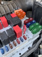
So I removed the Engine bay Fuse box (B001) and then checked all wiring and re installed. Apart from a few fasteners missing it all seemed OK.

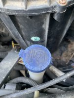
The state of the dashboard was to find the mouse (unfortunately I didn’t) as there was one at some point as shown on the washer bottle lid.

I think the mouse has since vacated and if not it sure has now as I did a 2h drive. Inhumane to some but there was no odd “smells” hence why I think it moved on.

Since putting the box back on I decided to start the steps again as you mentioned.
I removed T02 and then bridged the connection and voila… we have dipped beam.

So I ordered a couple of new relays.

I’m still not sure that it was 100% the cause as there was another “issue” when testing.

When pressing the hazard lights (dashboard loose) I heard a fan starting up and then got the “water in diesel” light on… I pressed it 3x and did the same.

Turned the ignition on pressed it again and the hazards came on as they should. Although one of the bulbs blew 🤣

So in summary… hopefully dipped beams will work when new relay arrives. I will take a trip to a local scrap yard to find new fasteners and screws for the dash (as a lot were missing/broken)

And I will keep an eye on the hazards.

Now to read up and start a new thread on the headlights as the 18 year old yellow ones are driving me mad 🤣🤣

Thanks again kind Sir.
 

Attachments

  • IMG_3158.jpeg
    IMG_3158.jpeg
    1.7 MB · Views: 36
  • IMG_3157.jpeg
    IMG_3157.jpeg
    1.6 MB · Views: 45
  • IMG_3155.jpeg
    IMG_3155.jpeg
    2.8 MB · Views: 92
Thank you for this.

I have my own little folder on the laptop with your documents. Greatly appreciated.

So I removed the Engine bay Fuse box (B001) and then checked all wiring and re installed. Apart from a few fasteners missing it all seemed OK.

The state of the dashboard was to find the mouse (unfortunately I didn’t) as there was one at some point as shown on the washer bottle lid.

I think the mouse has since vacated and if not it sure has now as I did a 2h drive. Inhumane to some but there was no odd “smells” hence why I think it moved on.

Since putting the box back on I decided to start the steps again as you mentioned.
I removed T02 and then bridged the connection and voila… we have dipped beam.

So I ordered a couple of new relays.


I’m still not sure that it was 100% the cause as there was another “issue” when testing.

When pressing the hazard lights (dashboard loose) I heard a fan starting up and then got the “water in diesel” light on… I pressed it 3x and did the same.

Turned the ignition on pressed it again and the hazards came on as they should. Although one of the bulbs blew 🤣

So in summary… hopefully dipped beams will work when new relay arrives. I will take a trip to a local scrap yard to find new fasteners and screws for the dash (as a lot were missing/broken)

And I will keep an eye on the hazards.

Now to read up and start a new thread on the headlights as the 18 year old yellow ones are driving me mad 🤣🤣

Thanks again kind Sir.
I am sorry, but you have misunderstood the purpose of bridging the relay contacts, which was to prove the wiring only. The next test of applying a test earth at the Switch Control Panel would have proved the relay. May I suggest that you still carry out this test, as the existing relay may be good.
 
I am sorry, but you have misunderstood the purpose of bridging the relay contacts, which was to prove the wiring only. The next test of applying a test earth at the Switch Control Panel would have proved the relay. May I suggest that you still carry out this test, as the existing relay may be good.
Oooops!

Sorry, yes misunderstood. I will try this later today once home.

Thanks
 
I am sorry, but you have misunderstood the purpose of bridging the relay contacts, which was to prove the wiring only. The next test of applying a test earth at the Switch Control Panel would have proved the relay. May I suggest that you still carry out this test, as the existing relay may be good.
Ok so I did the rest.

(Also new relay arrived today. Didn’t solve the issue)

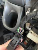
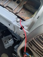
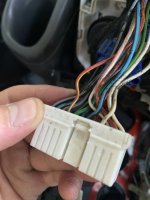
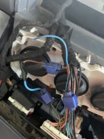
I did all the other points (pictures below)

A8 was easy to find and result were it worked.

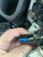
B4 was trickier as I thought I had the wrong plug but based on your information it seemed logical even though the red was more pink. All the cables seem abit “bodged” in there.

Result - fail

No dipped beam.

Was it the correct cable?

Also I now only seem to have 1 sidelight so I can only but assume the bulb has blown with all the messing about.

Thoughts on B4?

Thanks.
 

Attachments

  • IMG_3172.jpeg
    IMG_3172.jpeg
    1.7 MB · Views: 46
  • IMG_3173.jpeg
    IMG_3173.jpeg
    1.8 MB · Views: 40
  • IMG_3174.jpeg
    IMG_3174.jpeg
    1.8 MB · Views: 41
  • IMG_3175.jpeg
    IMG_3175.jpeg
    2.3 MB · Views: 41
  • IMG_3176.jpeg
    IMG_3176.jpeg
    1.4 MB · Views: 304
  • IMG_3177.jpeg
    IMG_3177.jpeg
    1.6 MB · Views: 44
  • IMG_3178.jpeg
    IMG_3178.jpeg
    2.7 MB · Views: 106
  • IMG_3179.jpeg
    IMG_3179.jpeg
    1.9 MB · Views: 42
Last edited:
I just changed the bulb over and it was NOT the bulb.

And I can’t seem to find the fuse that relates to the NS side lamp.
 
Ok so I did the rest.

(Also new relay arrived today. Didn’t solve the issue)

I did all the other points (pictures below)

A8 was easy to find and result were it worked.
The dipped headlight supply and relay are proved OK.
B4 was trickier as I thought I had the wrong plug but based on your information it seemed logical even though the red was more pink. All the cables seem abit “bodged” in there.
Column Switch (H005) connector B4 should connect to Switch Control Panel (H090) D17, also as stated in another post H090 needs 12V from instrument panel fuse F24, which in turn is supplied via sidelights switch. This part is very convoluted and passes through the ignition switch twice. As you have one sidelight can we assume that there is a supply to F24. Is it getting from F24 to H090 A2? This latter part is all on Sidelights diagram E2010, and we are trying to fault the Dipped Headlights!
Result - fail
See above.
No dipped beam.
Again see above.
Was it the correct cable?

Also I now only seem to have 1 sidelight so I can only but assume the bulb has blown with all the messing about.
For sidelight fuse location see E2010, or my diagram of LH Cab Fuse Panel (B002).
Thoughts on B4?
Presumably you did have ignition on?
I just changed the bulb over and it was NOT the bulb.

And I can’t seem to find the fuse that relates to the NS side lamp.
See above.
To summarise the dipped headlights require headlights on, which should of course put the sidelights and insrrument lights on. The instrument lights supply from F24 needs to connect to the switch control panel, before it will repeat the headlights on (earth or active low) signal, to the dipped headlights relay, which again requires the ignition switch on. I am not sure whether the switch control panel passes the headlght signal through, or uses it to connect a separate earth connection to the headlamp relay. However with this in mind perhaps it would be worth checking for earth at H090 B1 (black wire). I suspect that H090 requires this earth for correct operation.

My main suggestion is to prove the function of switch control panel, but you may wish to try a temporary bypass to prove everything else in the dipped headlamp circuit instead.

The reasoning behind all this interlocking is not obvious, and I worked in industries where interlocking was paramount
 

Attachments

  • Fusebox B002 Cab LH.pdf
    194.3 KB · Views: 45
  • H090 Switch Control Panel.pdf
    78.8 KB · Views: 42
  • eLearn E2010 Side & Rear Lights.pdf
    88.1 KB · Views: 42
The dipped headlight supply and relay are proved OK.
Great!
Column Switch (H005) connector B4 should connect to Switch Control Panel (H090) D17
I saw on another post you commented on about bridging H090 D17 to H090 A8 and then the "stalk" worked.
I tried this and the stalk still did not work.
For sidelight fuse location see E2010, or my diagram of LH Cab Fuse Panel (B002).
This fuse is a 15A instead of the 5A as per diagram. This fuse is intact.
Presumably you did have ignition on?
This was meant to be clarification that I did indeed find B4. Apologies for the confusion.
However with this in mind perhaps it would be worth checking for earth at H090 B1 (black wire)
I briefly tried this before leaving for work. I bridged the black wire to a new earth. No change in the result nothing happened but will spend more time later. This wire has been cut at some point and a connecter putting it back together again.
My main suggestion is to prove the function of switch control panel, but you may wish to try a temporary bypass to prove everything else in the dipped headlamp circuit instead.
Do you mean from H090 D17 to H090 A8 as per above?

Thanks
 
Ok you won't believe this but i've found the issue. (well you might believe it as you have been in the industry)

The fix:

Fuse F24 was the 1st thing I checked and was OK but replaced with a 15A instead of the 5A

After all the above testing etc the 15A fuse was still OK.

For some reason a voice in my head said to check the removed glovebox and ironically inside the removed glovebox was an unblown 15A fuse...
So...
OK what message am I receiving here...
I replaced the GOOD 15A Fuse F24 with the one found in the glovebox (another 15A)

Ignition on and bam.... we have dash lights AND dipped lights... but no indicators at all...
Ignition of, left for 15 seconds, back on and now the indicators work!! (How??)
At this point I realised that the FR indicator was no longer blinking "fast" as it was previously. Yep the bulb was working which previously wasnt...

So for science I wanted repetition and replaced F24 again with the other. No dipped beam!!!
So for now the 15A is back in and working again. I assume to replace this with a 5A?

The ONLY issue I still have is the FL/NS Side light is still inactive despite working before.

This all seems rather odd any ideas?

Thanks
 
That was my thread, I just lost the lights again today, this time it was a different dash fuse that went. HaVe you gone through all the fuses to double check them all?
Hi all,

Sorry I know this has been discussed to death and even this recent post https://www.fiatforum.com/threads/no-dipped-beam-height-adjuster-buzzing-2003-ducato-2-8-motorhome-base.509374/ didn't resolve the issue.

The fuse mentioned in this post has been upgraded to 15A and is OK.

Also mentioned on that post in the Relay box in the engine bay... Mine has the issue of wiggling it and the side lights will go out one side etc. So annoying.

However trying pretty much everything I can see online I still have no dipped beam.
The cab is an absolute mess right now as I have tried to find anything else (mouse chewed etc)

The van was recently purchased I will add.

Thanks in advance.

Sam
 
That was my thread, I just lost the lights again today, this time it was a different dash fuse that went. HaVe you gone through all the fuses to double check them all?
I need to find out why I have only lost 1 sidelight now.

I will manually go through all of them tomorrow. However just 1 side is odd because they appear to both be supplied by F24
 
I need to find out why I have only lost 1 sidelight now.

I will manually go through all of them tomorrow. However just 1 side is odd because they appear to both be supplied by F24
The guy commenting on my post @Communicator I think seems to know his stuff. My next stop will be a new relay. Although the 20a fuse might have blown because the wires for the socket were loose on the floor and might have got shorted. Although I was fairly sure this was completely dead 🤔
 
Ok you won't believe this but i've found the issue. (well you might believe it as you have been in the industry)
I have not worked in the automotive industry, but in my youth I was on very friendly terms with a rural garage owner, and assisted with electrical problems on a voluntary basis at weekends. Not all one way as I could use some of the workshop facilites for my own vehicle.
The fix:

Fuse F24 was the 1st thing I checked and was OK but replaced with a 15A instead of the 5A

After all the above testing etc the 15A fuse was still OK.

For some reason a voice in my head said to check the removed glovebox and ironically inside the removed glovebox was an unblown 15A fuse...
So...
OK what message am I receiving here...
I replaced the GOOD 15A Fuse F24 with the one found in the glovebox (another 15A)

Ignition on and bam.... we have dash lights AND dipped lights... but no indicators at all...
Ignition of, left for 15 seconds, back on and now the indicators work!! (How??)
At this point I realised that the FR indicator was no longer blinking "fast" as it was previously. Yep the bulb was working which previously wasnt...

So for science I wanted repetition and replaced F24 again with the other. No dipped beam!!!
So for now the 15A is back in and working again. I assume to replace this with a 5A?
As I have stated on another thread, in similar words, the heating effect of an electric current is proportional to the square of the current, so leaving a 15A fuses in situ, where a 5A fuse is specified increases the energy supplied to a possible fault 9 times. This could result in a vehicle wiring fire, should a fault occur.
The ONLY issue I still have is the FL/NS Side light is still inactive despite working before.
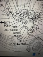
See diagram E2010. LHS sidelight shares fuse F12 with RHS rearlight. The splitting point is D097A referred as a "short circuit coupling", which is a translation failure, read "linking coupling" instead, and it makes sense. Unfortunately if I have correctly identified D097 as a stack of connectors forward of and below the radio, normally inaccessible or perhaps you have excavated that deep? For confirming contuiity of circuits, I often recommend using a simple 12V filament, not LED, test lamp, connected to 12V, or earth as applicable. It will not light via a high resistance connection, while a multimeter would give a plausible voltage reading.
.

This all seems rather odd any ideas?

Thanks
I am pleased that you are making progress.
 
I have not worked in the automotive industry, but in my youth I was on very friendly terms with a rural garage owner, and assisted with electrical problems on a voluntary basis at weekends. Not all one way as I could use some of the workshop facilites for my own vehicle.

As I have stated on another thread, in similar words, the heating effect of an electric current is proportional to the square of the current, so leaving a 15A fuses in situ, where a 5A fuse is specified increases the energy supplied to a possible fault 9 times. This could result in a vehicle wiring fire, should a fault occur.

See diagram E2010. LHS sidelight shares fuse F12 with RHS rearlight. The splitting point is D097A referred as a "short circuit coupling", which is a translation failure, read "linking coupling" instead, and it makes sense. Unfortunately if I have correctly identified D097 as a stack of connectors forward of and below the radio, normally inaccessible or perhaps you have excavated that deep? For confirming contuiity of circuits, I often recommend using a simple 12V filament, not LED, test lamp, connected to 12V, or earth as applicable. It will not light via a high resistance connection, while a multimeter would give a plausible voltage reading.
.


I am pleased that you are making progress.
Ok we have working lights 100%!

I may have found your elusive D097A? Based on the dash layout it appears to be deep behind the steering column? I was unable to get more than just my phone down there to record it for you.

Upon further testing of your wiring diagram I checked the fuses. F12 was OK. However… based on the previous experience with F24 I decided to change it with another 5A that was OK.

Guess what… the sidelight worked…

So conclusion to next steps.

I will order a complete set of “decent” fuses (plus spares) and change them all as per your diagrams. I noticed that there are a few of higher amps been swapped and no idea why.

I would like to appreciate you and your methods as well as patience. I hope this will be the end of it and I will update again once changing all fuses.

Thanks again
 

Attachments

  • IMG_3189.jpeg
    IMG_3189.jpeg
    2.7 MB · Views: 213
  • IMG_3193.mov
    70.5 MB
  • IMG_3205.jpeg
    IMG_3205.jpeg
    1.9 MB · Views: 158
Last edited:
Ok we have working lights 100%!

I may have found your elusive D097A? Based on the dash layout it appears to be deep behind the steering column? I was unable to get more than just my phone down there to record it for you.

Upon further testing of your wiring diagram I checked the fuses. F12 was OK. However… based on the previous experience with F24 I decided to change it with another 5A that was OK.

Guess what… the sidelight worked…

So conclusion to next steps.

I will order a complete set of “decent” fuses (plus spares) and change them all as per your diagrams. I noticed that there are a few of higher amps been swapped and no idea why.

I would like to appreciate you and your methods as well as patience. I hope this will be the end of it and I will update again once changing all fuses.

Thanks again
This comment is mainly aimed at Communicator but was the video I took for D097A?

I do have a couple of questions please if I may?

1. As per your diagrams and the actual fuse boxes in the car there are quite a few with higher Amps. Is this due to "laziness" or would any of these been upgraded for legitimate reason?

2. I'm about to replace all the fuses with MTA branded fuses. Should I replace like for like or go back to the original as per you diagram?

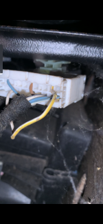
3. Not that I can get to this plug but I paused the video and does it appear to you like a cable has frayed? (picture below)

4. If upgrading all headlight bulbs to LED's (not going into the legalities or not) would the current Fuses be OK as I know LED's have less Ampage.

Thanks
 

Attachments

  • IMG_3206.png
    IMG_3206.png
    3.8 MB · Views: 32
This comment is mainly aimed at Communicator but was the video I took for D097A?

I do have a couple of questions please if I may?

1. As per your diagrams and the actual fuse boxes in the car there are quite a few with higher Amps. Is this due to "laziness" or would any of these been upgraded for legitimate reason?
My diagrams relate to the OEM fitting and or Drivers Manual. I cannot immediatly see any legitimate reason to increase the ratings

2. I'm about to replace all the fuses with MTA branded fuses. Should I replace like for like or go back to the original as per you diagram?
I would be inclined to revert to designated ratings.
3. Not that I can get to this plug but I paused the video and does it appear to you like a cable has frayed? (picture below)
If you are looking at the yellow/white wire it may have suffered mechanical damage, perhaps knawed by a mouse. Close inspection were it possible could determine. I do not think that the photo is of D097, which must be a stack of connectors, as it can have most suffixes from A to M.
4. If upgrading all headlight bulbs to LED's (not going into the legalities or not) would the current Fuses be OK as I know LED's have less Ampage.
I do not favour non OEM LED headlights, as they can cause serious glare problems to oncoming drivers. You could take the opportunity to reduce the fuse rating, but this not essential as the fuses function is to protect the wiring.
 
I would be inclined to revert to designated ratings.
I have now installed all new Fuses as per designated ratings. Some contacts in the fuse box has corrosion so cleaned them up.
I do not think that the photo is of D097, which must be a stack of connectors, as it can have most suffixes from A to M.
Before putting it all back together I think I may have found it. Certainly a "stack" of connectors located below the radio behind the heater switches.

Seems most accessible via the hole from removing the glove box.
I do not favour non OEM LED headlights, as they can cause serious glare problems to oncoming drivers. You could take the opportunity to reduce the fuse rating, but this not essential as the fuses function is to protect the wiring.
I have it booked in for an MOT with them in to test the light patterns etc. I have all originals in case it really is a danger to other users.
 

Attachments

  • IMG_3224.jpeg
    IMG_3224.jpeg
    1.9 MB · Views: 25
  • IMG_3225.jpeg
    IMG_3225.jpeg
    1.6 MB · Views: 32
  • IMG_3226.jpeg
    IMG_3226.jpeg
    1.5 MB · Views: 29
  • IMG_3228.jpeg
    IMG_3228.jpeg
    1.5 MB · Views: 30
  • IMG_3229.jpeg
    IMG_3229.jpeg
    1.7 MB · Views: 27
  • IMG_3230.jpeg
    IMG_3230.jpeg
    1.5 MB · Views: 28
Back
Top