Technical Ducato engine cooling fan power ratings

Currently reading:
Technical Ducato engine cooling fan power ratings

NZAndy

New member
Joined
Feb 22, 2023
Messages
6
Points
2
Location
Te Kuiti, New Zealand
I have a

Fiat Ducato 2007

Diesel Van 120 Multijet 2.3 D

FWD -- 250_ 2287cc 88KW 120HP F1AE0481D

ZFA 25000001146015

I need a twin radiator cooling fan. I can’t find the OEM number (not sure where it is stamped and the old fans are still in van). My van has manual climate control (air con), no relay or resistor attached to the fan shoud. Just the plugs into the fan motors

When I search there are lots that are apparently compatible with my van. Beside the different manufactures and prices the only difference seems to be the fans power ratings ( eg 300/400W, 200/300W, 187/300W , 300/300 or none given). DOES IT MATTER?? (On my van one fan has 7 blades the other 9 blades, where all the fans on eBay seem to have both fans with 7 blades.)

How do I decide which one to choose for my van? Are any brands / manufactures better than others?
Andy
 
Hi Andy,

I have not tried this myself, but if you put your VIN into ePER (see top of page) you should be able to find part numbere for the original equipment on your vehicle.
I am curious to learn what has happened to the original fans, as I do not remember Te Kuiti as being in a mountainous area.
 
Hi Andy,

I have not tried this myself, but if you put your VIN into ePER (see top of page) you should be able to find part numbere for the original equipment on your vehicle.
I am curious to learn what has happened to the original fans, as I do not remember Te Kuiti as being in a mountainous area.
Hi Andy,

I have not tried this myself, but if you put your VIN into ePER (see top of page) you should be able to find part numbere for the original equipment on your vehicle.
I am curious to learn what has happened to the original fans, as I do not remember Te Kuiti as being in a mountainous area.
Thanks Communicator for your reply .
The ePER was helpful. I found some on ebay at about a quarter to half of the cost of what I could get one for on NZ. Only problem they won't ship to NZ or the cost is prohibitive.
I have found a secondhand fan motor in NZ and fitted it. It was only one fan that had a stuffed motor - stuffed bearing and burnt out - causing the fuse to blow.
Replacement goes fine but turns on as soon as you start the engine (engine cold) and turns off when you stop the engine. Not sure if it should do this??
For your information Te Kuiti has hills but not mountains. I suspect that the fan had not been working for some time. Was alerted to the problem when going over Arthur's Pass (Southern Alps in South Is) on of steepest roads in NZ. Temp warning light came on!!
Up until then and since without fixing the fan the temp gauge is always at halfway.
 
Hi NZAndy

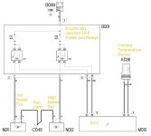
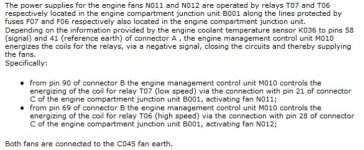
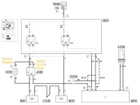
I attach schematics of the fans extracted from eLearn. The fans are relay controlled, with the two relay coils controlled by the ECU on the basis of engine temperature information from the coolant temperature sensor. The latter is a negative temperature coefficient (NTC) thermistor. The sensor resistance specification is 2080 ohms at 25C dropping smoothly to 115 ohms at 80C. There is probably a +/- tolerance on these figures, but anything substantially different spells trouble.

With manual aircon there is a refinement where one fan can be run at low speed by using a series ballast resistor. This resistor can be shorted out by a third relay when full speed is needed. The aircon settings will therefore have some influence on fan speed. A fan at full speed needs substantial current - tens of amps - so connections including grounds must be good.

I don't think any fan(s) should run immediately from switch-on with the A/C disabled, and continuous running is likely to wear out the fan prematurely as well as over-cooling the engine. You might want to check the relays and the in-circuit drive voltages to their coils to see if the ECU is genuinely demanding cooling fans to run.

Most modern vehicles use software between the coolant sensor and the gauge, so that any acceptable temperature (say 80 to 95 C) gets displayed rock solid at the centre of the scale. It stops overly worried types from pestering their dealers but does mean you can't quite be sure what's going on.

Bear in mind that eLearn is not infallible, and your vehicle may differ in detail but this should give you an idea of the way Fiat do things.
 

Attachments

  • X250 Cooling Fan Schematic 1.jpg
    X250 Cooling Fan Schematic 1.jpg
    60.2 KB · Views: 36
  • X250 Engine Cooling Description.jpg
    X250 Engine Cooling Description.jpg
    70.3 KB · Views: 33
  • X250 Engine Cooling Fans with Aircon.jpg
    X250 Engine Cooling Fans with Aircon.jpg
    71.8 KB · Views: 32
Hi Anthony

Thanks for the info and schematics (mine is the one without the speed control and ballast resistor).
I had a good go at investigating what was going on with the multi-meter the other day.
Discovered the grey/brown wire from the ECU to the fuse/relay box pin 69 to pin 28 did not make continuity so added a wire to bypass the break. Thought this might solve my problem. BUT NO this now makes the T06 relay switch on and make the other fan N012 now also turn on when the engine starts!! (Looks as though that fan, N012 hasn't been working for some time as well and I suspect the reason the fan N011's motor was burnt out could likely have been because the fan was running all the time)

Found the pins 58 and 41 on the ECU plug. The resistance across them was a bit over 1000 ohms. That was when the motor was a bit warm so I think the sensor thermistor's resistance in K036 is probably OK

With the motor running and the relays pulled out I measured the voltages at pin 86 and 85 on both of the relays. One side was 13V the other side 0 V. which would suggest the current would flow when the relay is plugged in and switch the fan on (which is what is happening). How does the ECU switch the relay off? By supplying an equivalent voltage to the other side of the relay to stop the current flowing???

So I am at bit of a loss now. Any one with more knowledge and suggestions would be much appreciated.

Andy
 
Hi again Andy

The internal arrangements of the ECU are not in the public domain. However, it is commonplace for ECU outputs to be an "open collector" arrangement. This means a switching transistor is used, with its collector taken to the ECU output pin. When the ECU makes the transistor "on/conducting", current flows from +12 volts through the relay coil and through the transistor to ground inside the ECU. This current is typically 80 milliamps. When the transistor is "off/non-conducting" it presents a very high resistance and negligible current flows.

The operation can only be properly tested with a load (e.g. a relay coil or a resistor of about 150 ohms) connected between +12 volts and the ECU output, simply monitoring the unloaded ECU output with a voltmeter or ohmmeter will give ambiguous results.

It's possible that the ECU is faulty, and something is causing its fan relay output(s) to be permanently in the "on/conducting" state. If this is so, you can either replace the ECU ($$$$$$) or rig up some sort of workaround. The low-tech approach is a thermal switch in the cooling system wired to energise the fan relay coil (s). I don't know what's available in your local market, but for many years a firm called Kenlowe in the UK used to sell aftermarket electric cooling fans. Part of the setup was a slender thermal probe which could be placed in a coolant hose, and this actuated an temperature adjustable switch. Kenlowe only do OEM stuff nowadays, but you might find this part secondhand.
 
I do not have complete detailed info for the x250, and have been on a short trip without internet, so I in a catchup situation. The following may not be new to @NZAndy but given the problems encountered, I think that the "rusty junction" syndrome is worth mentioning. I have not seen it myself, but on the X250, there is a tubular member under the LHS headlight which can have its black paint rubbed off by abbrasion, gets rusty, and then wears through the wiring harness. Earth and open circuit faults can be the result. I am not sure of the provenance of the attached photo, but I think that it was posted by @Reg 65 who has previously posted on this particular source of problems.
 
Back
Top