IMG_7487 Large.jpeg

500 (Classic) Ducati powered Fiat from California

I have taken on the crazy task of trying to stuff a Ducati 1100 air cooled L-Twin engine in the back of my 1974 Fiat 500R, and solving all the challenges that will arise because of it!

Introduction

Hello everyone! As the title suggests, I have decided to build a Ducati powered Fiat 500!

I have restored a couple classic American cars, some motorcycles, and have designed and built a handful of Formula SAE cars in college, but I've always wanted to build my own motorcycle powered road car.

After a decade of working at one of the largest Spacecraft companies in California, I decided to take a break and try to make this dream a reality. The car needed to be simple, lightweight, relatively cheap, and older than 1975 (California smog requirements). I have a buddy that did this with an old Honda S600, and another with a Fiat 850 spider, but I wanted to do something a bit less roadster-y. Then, as the wife and I were honeymooning in Italy, I saw the answer: the old Cinquecento.

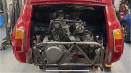
There seems to be lots of motorcycle powered 500s for hill climbing, and Z-Cars is one of the most popular swaps out there with their Suzuki Hayabusa swapped "Fiabusa" (they also make a Subaru swapped "Fubaru"), but I wanted to keep the motor air cooled (no big radiator up front) and Italian. After a bit of research, I decided to go with my favorite motorcycle engine, a Ducati 1100. The last of the big, air cooled, dry clutch L-Twins. How hilariously adorable would this car be with that noise coming out of it?

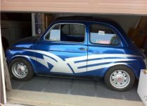
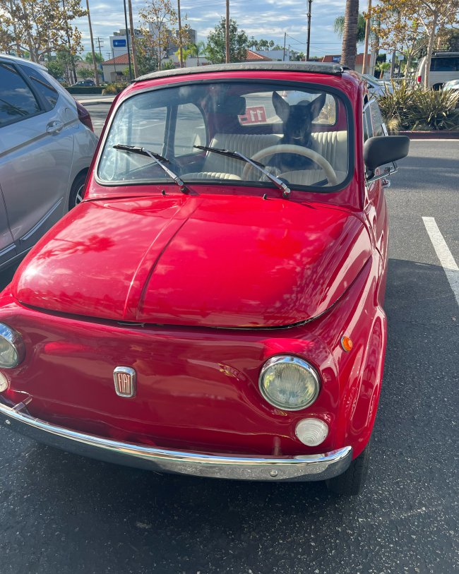
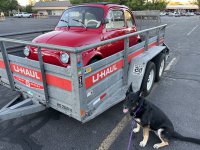
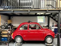
I spent a few months looking for the perfect car - something that was driveable, in decent shape, but not too nice, so I could save money up front and put it toward the swap. I ended up with a clean-ish 1974 Fiat 500 R with about 26,000 km on the clock that had been imported into the states a few years prior. The body was in pretty good shape until a strap broke towing it home resulting in a head on collision with the trailer. I minimally repaired the damaged area so I could turn the wheels full lock again, then drove it around a few months until I got the car registered.

Now that the car is legal, it's time to begin the project!

I'm looking forward to sharing the progress and hearing everyone's thoughts on the build. I have reached out to a few people individually and everyone has been extremely nice and very helpful!
  • Like
Reactions: porta and ben
That's interesting, I haven't heard of Ducati working with Fiat on this. I know Moto Guzzi had a proposal, but ended up not going through because Fiat didn't think Moto Guzzi could keep up with demand. More about that here:


I had originally looked at doing a Moto Guzzi and VW option (would have packaged nicer) but I'm too much of a Ducati fan boy having owned 3 of their motorcycles!

You are correct, it was Motor-Guzzi and NOT Ducati----but it would still be very interesting to see how they fitted the engine and what transmission they proposed to fit. I have seen the result of a VW engine fitted into a 500 when I was at Radbourne Racing.The car was called "The Little Red Rooster" and (I think it was) 'Hot-Car' magazine did an article on it---it was not a pretty conversion---the VW enine is just plain too big.
 
Quick update before I break for some major CAD design work on the rear suspesion and differential mounting assembly

Front Suspension

I welded in the front cross braces and shimmed/aligned all the control arms. I'm petty happy with the setup, just need massage the pinch welds for clearance at full bump. I'm running about +/- 40mm of travel (limiting rebound but could go more) with about -1.2 deg of static camber. I haven't set up the steering yet (will likely make a separate post for that) so we'll see how bad the bump steer is with this setup. I'm really don't want to make custom front uprights, like I have to for the rear!

IMG_7485 Large.jpeg


Engine Frame

On the last update, I had just started tacking together the engine frame, but was still missing the other half, some engine mounts, and the structure to connect the two. Well, now it's all (mostly) welded! I still need to add some gussets and clean up some of the welds, but I'm happy to move on to the next portion of the build - the differential frame. This will probably take a while to flush out, since this frame will hold the differential/reversing gearbox and the suspension (control arms, shocks). I want to make sure this all is lined up pretty well since there's not a ton of room under this thing.

IMG_7487 Large.jpeg
IMG_7489 Large.jpeg
IMG_7501 Large.jpeg
Neatly done engine frame; it will be interesting to see how you build the rear-end. Couple of questions---(1) how are you going to cool the engine? In the bike instalation you have the cold air created by the forward motion of the bike helping cool it, and with the original engine installation, you have a fan and (2) How much static camber? 1-2degrees is a lot of negative camber (static) which will increase when you put weight into the car (to-wit, the driver). On my own car I have a whiff of POSITIVE camber when the car is empty and static, although I set it up with a fair bit of weight in the front of the car with '0' camber. Toe-in (again with weight in the front of the car) is best at '0', and make sure that the track-rods are of the same length after any adjustment.
 
Neatly done engine frame; it will be interesting to see how you build the rear-end. Couple of questions---(1) how are you going to cool the engine? In the bike instalation you have the cold air created by the forward motion of the bike helping cool it, and with the original engine installation, you have a fan and (2) How much static camber? 1-2degrees is a lot of negative camber (static) which will increase when you put weight into the car (to-wit, the driver). On my own car I have a whiff of POSITIVE camber when the car is empty and static, although I set it up with a fair bit of weight in the front of the car with '0' camber. Toe-in (again with weight in the front of the car) is best at '0', and make sure that the track-rods are of the same length after any adjustment.

Thanks Tom!

The bike has a small oil cooler but no fan. I plan to have a much larger oil cooler (maybe 2 if I can package them) with fans and I also plan to put a fan aimed at the cylinder heads, drawing air under the car and out the back. I may need more louvres on the rear bonnet, or just leave it off all together on hot days or days I plan to drive it spiritedly. Cooling is one of my biggest concerns, but since this won't be a track weapon, I'm hopeful I can make it work.

Regarding camber, I have -1.2 degrees static camber, which climbs to about -3.5 degrees camber under full bump. I picked the camber curves based on how much roll I expect the car to see, and wanted to minimize how much the unloaded tire goes positive. These are totally different kinematics than stock, so I could see how you might want some static positive camber to get this thing to better behave in cornering or braking, especially depending on the tires!
 
Greetings! Transformation looks really good, can't wait to see the actual outcome of the build. I'd like to transform my 74 Fiat 500R into this set up if I can find a shop near me. (SoCal)
Thanks, glad to hear there's another classic Fiat 500 nearby!

I'll post a big update in a week or two, just wrapping up some rear suspension and chassis design before jumping into more fabrication.

This has been quite the project with lots of scope creep! I'm hoping to get to rolling chassis by end of year, driving in 2025. Let me know if you find a local shop who is willing to attempt such a project, I'd love to collaborate with them on this or future projects!
I am in Menifee, Ca by the way...

As of now, I am still searching for a good shop to work on mine, it needs a little body work and a fresh coat of paint as it has not been touched since I brought it over from Sicily in 2003. Do you know any shop you could recommend? It was running before but since I work overseas I do not have time to mess with it much. I thought about buying a new upgrade motor for it from Italy.

I'd like to come by to check out the progress of your project next time I am home in Nov if possible.
 

Attachments

  • 74 Fiat 500R.jpg
    74 Fiat 500R.jpg
    145.3 KB · Views: 38
I am in Menifee, Ca by the way...

As of now, I am still searching for a good shop to work on mine, it needs a little body work and a fresh coat of paint as it has not been touched since I brought it over from Sicily in 2003. Do you know any shop you could recommend? It was running before but since I work overseas I do not have time to mess with it much. I thought about buying a new upgrade motor for it from Italy.

I'd like to come by to check out the progress of your project next time I am home in Nov if possible.
No problem, send me a DM when you're in the area!
 
Hey Everyone! It's been a little over months since my last update where I finished building out the front suspension and the rear engine frame that holds the Ducati motor. Since then I've been designing the rear suspension, differential frame, and the connections to the vehicle. I wanted to share with you a quick update on the design before I get deep into the build!

Suspension Design
Now that the front is built and I know my front travel, ride frequency, roll center height, and camber curve, I used that information to design the rear suspension. I iterated in a 2D sketch to get points that work with the existing body, placement of differential, and engine output shaft, as well as fine tuning the motion ratio so that it works with my GAZ shocks. Because I'm designing a double wishbone suspension, I also needed a custom upright to attach my control arms and hold the stock Fiat hub. This went through quite a few design iterations, mainly due to integration of the shock into the lower control arm, before I came up with something I was happy with. I used VSUSP.com as a crude but free suspension kinematic software to make everything looked reasonable, then went onto designing the frame!

1725813544324.png


Component Design
For the frame, I had initially tried to design everything using square tubing, since there's less welding and it would provide a good mounting surface for the suspension and differential, but I ended up switching to a plate based weldment. I can get plates laser cut pretty reasonably (thanks Send Cut Send!) and that allows me to adjust thickness throughout the structure and have locating holes for the different mount points (I hate drilling through tubes, they're never square!). A plate weldment also made the most sense for the uprights and A-Arms, where I could use the parts to locate each other and tie into my spherical and shock mounts. After lots and lots of iteration, I came up with the design below:

1725813863256.png


Connecting it All Together
Now that the differential frame is designed and the engine frame is designed (and built), it's time to connect the two and anchor them to the car. Unfortunately, the diff frame designer (current me) and the engine frame designer (me from 5 months ago) didn't talk to each other, so I did not have a clean way to connect the two frames. Since I wanted to keep the rear seats, the diff is much lower than the engine, and because CV angle is a big concern, I have the engine and differential very close together. This makes for a tricky envelope to connect the two frames and clear the Engine/Differential drive built. I solved with some blank off plates and and mitered tubes. It's not the prettiest solution, but luckily this portion of the frame will be well hidden. To connect the forward end of the frame, I am running a rectangular tube across the Fiat's lower suspension arm pickup point and using this tube to anchor to tie multiple tubes to the differential frame. See below:

1725834071994.png


I spent a bit of time running Finite Element Analysis (FEA) through Fusion 360 to get some rough stress and defection numbers for various load cases. It's not the most accurate, so I'm holding pretty healthy safety factors, but the structure is mainly stiffness driven, and this tool gave me some good comparative info on how best to stiffen the structure. I am most worried about deformation between the diff and engine since too much deformation will cause the drive belt between the engine and diff to be very unhappy (misalignment or tension). After I got this number down under a pretty extreme load case (3G bump and 2G side load), I sent all my part files to get laser cut!

1725834545105.png


Next up: I should get all the parts in the next couple weeks and will spend the following few weeks fabricating the rest of this frame. I want to hold off on the control arms until I have the complete frame installed, so I can make sure the wheels fit correctly (it's easy to change position of the wheel with modified A-Arms). I also need to check those CV angles, it'll be tight!

Attachments

  • 1725813181711.png
    1725813181711.png
    193.9 KB · Views: 60
  • 1725813482315.png
    1725813482315.png
    248.2 KB · Views: 56
  • 1725813857104.png
    1725813857104.png
    416 KB · Views: 57
  • Like
Reactions: jackwhoo and porta
It's been a couple months since my last update, but I made a lot of progress on the differential frame for this car! The frame is pretty much all welded, minus some gussets. I've got a few different sets of shim stacks to shift the differential within the frame, so that the belt can be tightened/loosened, or so I can fine tune the differential alignment with respect to the motor output shaft.

1731708249085.png


I also made a jig to hold the motor frame with respect to the differential frame so that I can get the two aligned before joining them together. This will be critical in aligning the two belt pulleys since I don't have a lot of tolerance for belt misalignment.

1731708431088.png


My original plan was to align these two frames then notch and weld tubes to join them permanently, but after looking at the tight clearances in real life (vs in CAD) I decided In need to redesign that portion of the frame to include a bolted split plane. This will allow me to better service the differential without requiring the engine to be removed. So back to the drawing board!

1731712657508.png


Next up: Making the custom driveshaft to mount the engine side drive pulley, finish joining the two frames together, and then work on installing the assembly into the car and welding up the final braces!
After a few slow months I have finally installed the Ducati engine and Elite differential into the Fiat!

The biggest challenge was finalizing the belt drive components and getting everything aligned. I ended up redesigning the part to consist of a laser cut splined piece (connecting to the engine output shaft) that bolts to a machined driveshaft that connects to the belt pulley. This worked much better than any welded assembly I could have made!

1743455477632.png


Once I knew were the engine side pulley was, I needed to align the differential frame to the engine. Drive belts, unlike chains, can only tolerate about .25 deg of misalignment, and with these pulleys being so close, I needed to get them aligned as close as possible. After what seemed like an eternity of aligning and jigging, I finally welded the two frames together!

1743455626639.png


Now that the two frames were joined, it was time to install them in the car. After a roughly positioning the frame, I wasn't happy with the location of the diff with respect to the wheel arches. These CV angles are already pretty high, so I decided to redesign the mounts to shift everything a bit further back, reducing the CV angles by about 5 degrees. Since I was committed to redesigning the mount, I also incorporated a polyurethane interface to help reduce some of the engine vibration making its way into the car.

1743455874417.png


With the new mounts installed and the frame in place, it was time to add the last few tubes and officially get this engine and differential installed!

1743454960244.png

I'm pretty happy with how it came out. Everything clears the rear panel and engine bonnet, but I can totally see myself running this thing without those items, just like in the picture above, with some type of custom bumper to not hide the engine. What do you guys think?

Next up: Rear Suspension!

Attachments

  • 1743454777493.png
    1743454777493.png
    392.6 KB · Views: 4
  • 1743454851441.png
    1743454851441.png
    392.6 KB · Views: 4
Awesome, totally mad but awesome no doubt about it.

Keep at it, I need to see that rip down the road 😀
Hi Bobby;
Your nearly there! With regard to the "engine cover" conundrum, why not do a 'classic Abarth' and hinge the engine cover at the top (I can send photos and what sort of hinges if you want) and engine cover braces---if you can design and make that engine/gear-box mount, engine-cover braces will be a 'piece of cake' for you---again, I can send you pictures. By doing it that way, the engine will be protected, the engine-cover is able to be swung totally out of the way if you need to work on it, AND it will look very "Abarth" (that is until one pokes their nose under it!)

Hey Tom, that's definitely an option I've considered. The Rear Panel does block a significant portion of the engine since it's mounted so low, but if you can still see all the moving bits (dry clutch via open cover, timing belts) with the Abarth setup, I'll probably go that approach!

1743521815533.png
 
It's coming together well! Nice to see it following through ,as I know sometimes it's easy to have big ideas and then when the problems hit the projects stall, but you seem to be solving those problems well.

Do you have a plan for cooling?The standard Fiat engine has a pretty big fan driving air over the air cooled cylinders, and on the bike that engine would be in full air flow, even then sometimes the rear cylinder is jetted/mapped richer to account for it running hotter. You could maybe try and duct air from under the car? Or do you have a plan for forced air flow?
Thanks!

Yes, cooling will be one of my biggest challenges. I will increase the size of the stock oil cooler and add a fan, but will also have a duct with a fan running from the underside of the car, blowing air toward the cylinders. The hope is that since this motor has two individual cylinders that need cooling, I don't need a fan with a lot of pressure capability (like most multi cylinder car engines) and can just use something with lots of flow.

Excited to get into solving that problem in a few months!
 
Back
Top