

Introduction
This document is heavily based on the instructions in the service manual but with any additional notes gathered from forum members' own experiences. The illustrations from the manual have been renumbered to match the bullet numbers in this guide for clarity. The whole service manual is available here:

 www.fiatforum.com
I'll be doing this for my Barchetta in the next month or so (Feb 2025) and will hopefully be able to add a few photos and observations of my own.
Relevant threads:
www.fiatforum.com
Special tools required:
1895879000
1860847000 camshaft locks - definitely required to lock the camshaft in place
18... flywheel retainer
Tools to re-tension the belt (believed unecessary by @suoixon):
1860831000 leverage tool

1860845000 tensioner tool

Some general comments from @s130
Firstly, the auxiliary component belt needs to be removed
REMOVING-REFITTING AUXILIARY COMPONENT BELT
Position the vehicle on a lift (or get ready to jack it up and put it on axle stands), disconnect battery negative lead and then proceed as follows:
1. Loosen nuts retaining right front wheel

2. Raise vehicle and remove right front wheel. Unscrew the bolts fastening passenger side wheel arch lining and remove from vehicle
Notes from @Davefridge - 2 of the screws are shorter than the rest, make a note of where they come from. Rectangular cover includes 1 plastic rivet. Just push the centre part through to release it. As to removing the liner itself, it is one big struggle!

 Check tension and condition of auxiliary unit drive belt and in particular for cracks,tears,surface wear(which looks smooth and shiny) and dry or hardened parts that could lead to loss of grip. If one of the above defects is found, replace the belt.
3. View of auxiliary drive belt fitted to vehicle:
Avoid the belt coming into contact with oil or solvent that could impair the flexibility of the rubber with a consequent loss of grip

4. Slacken belt tension by turning central automatic tensioner nut anticlockwise in order to release pressure on the spring inside the device
@Davefridge again. The tensioner nut is 15mm. To increase the leverage of a regular spanner, I slipped a much larger spanner over it (see 1st photo).


5. Prise off the auxiliary drive belt while keeping the tensioning device slack.

Reverse disassembly instructions in order to fit a new belt. The preloaded automatic tensioner spring will ensure belt tension is correct after turning the crankshaft a few times
REMOVING-REFITTING TIMING BELT
6. Remove the fixed belt pulley to permit removal of the timing belt guard

7. Remove the lower bolts retaining the timing belt guard
@Davefridge The 3 lower & 3 upper screws are Ribe keys. You can use a Torx T40 instead. The middle 2 screws are 5mm Allen keys. I removed the header tank fixings to give better access to the top 3 cover fixings or you could remove the header tank altogether. I used a mini ratchet with T40 Torx bit (see photos 2&3). The left hand upper screw is exceptionally difficult to get to!!

8. Unscrew top timing belt cover retaining bolts, then remove the cover from the engine bay.

9. Remove the ignition coil cover by unscrewing the bolts shown in the figure. Hexagonal-headed socket screws (1) may be exposed by removing oil filler cap

10. Disconnect supply leads to ignition coils, earth lead (1) and pipe (2) for recovery of oil vapour from the cylinder head cover

11. Disconnect the electrical connection shown in the figure from the air conditioner compressor
Obviously only applies if you've got aircon. @Davefridge Very difficult to get at! Connector is like the coil pack connectors. Squeeze the outer and it should pull apart. (difficult with a big pipe in the way!)

12. Remove the cylinder head cover by undoing the retaining bolts shown in the figure

13. Remove the spark plugs using an appropriate wrench

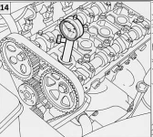
14. Position the gauge against cylinder no. 1, then use tool 1895879000 to turn the crankshaft to t.d.c
@Davefridge Before locking the cams I removed the auxiliary drive pulley from the crankshaft (step 18). I locked the crankshaft by wedging a prybar into the flywheel through the lower cover (step 17 below)
To turn engine over I used a socket, 14" extension to clear bodywork and a 16" knuckle bar on the crankshaft nut. A piece of dowel in cylinder No1 spark plug hole is sufficient to judge TDC. When finding TDC the cam lobes on cylinder No1 inlet shaft should be facing towards the rear of the car.

Alternatively, according to @suoixon:
15. Remove the 2nd intake end camshaft cap and the 3rd exhaust end camshaft cap as shown in the figure

Mark camshaft caps after removal to ensure they are refitted in the correct position. Otherwise camshafts may operate inefficiently
16. Position and retain pair of tools 1860847000 on caps removed previously.

Tool pair 1860847000 must follow camshaft cam profile exactly
17. Remove the protective cover on the bell housing shown in the figure, then position flywheel retainer 18.... (who knows what this tool number is - @Davefridge used a prybar by the sounds of it!)

18. Remove auxiliary drive pulley on the crankshaft

19. Check that the locating dowel on the crankshaft drive gear is positioned low down in line with the engine. Then remove the inspection cover on the bell housing and check that the reference mark on the flywheel coincides with the mark on the bell housing, as shown in the box

20-21. Slacken drive belt tension by undoing the nut shown in the figure, then prise off the belt.
@Davefridge Slacken the belt tensioner. What they don't tell you is that if you re-tighten it in its "loosest" position the belt is much easier to remove and re-fit!


REFITTING TIMING BELT
22. To facilitate timing belt positioning, loosen intake end camshaft pulley bolt by applying leverage with tool 1860831000

23. Fit the belt, observing the following fitting order:
Fit the belt so that the arrow on the belt points in the direction of engine rotation

24. Fit tool 1860845000 into the hole on the automatic tensioner mount. Turn the tool to exercise a force on the automatic tensioner. Adjust to maximum tension and then tighten nut retaining tensioner to mount

Again an alternative approach from @suoixon:
25. Tighten bolt retaining intake end camshaft pulley to a torque of 11.8 daNm. Applyleverage using tool 1860831 000.

26. Remove tool pair 1860847000 and reposition camshaft caps (marked upon removal) correctly. Tighten to a torque of 1.5 daNm. Remove the flywheel retainer and turn crankshaft through two turns in its direction of rotation.
Loosen belt tensioner retaining nut and use tool 1860845000 to align mobile belt tensioner pointer (1) with fixed reference (2) on engine block. Tighten belt tensioner retaining nut to a torque of 2.5 daNm and then refit parts removed previously

This document is heavily based on the instructions in the service manual but with any additional notes gathered from forum members' own experiences. The illustrations from the manual have been renumbered to match the bullet numbers in this guide for clarity. The whole service manual is available here:
Service manual - restructured
This section is a restructuring of the original Service manual upload to the forum in an attempt to make it easier to download and navigate the PDF files. The originals are still there if this changed structure doesn't suit you. I should say...
I'll be doing this for my Barchetta in the next month or so (Feb 2025) and will hopefully be able to add a few photos and observations of my own.
Relevant threads:
Replacing Timing Belt | FIAT Barchetta
Hello, I am preparing to change the timing belt, tensioner and water pump on my 1997 Barchetta. I note in the manual that the intake end camshaft pulley bolt needs to be loosened in order to facilitate timing belt positioning Is this really necessary Also does the water pump need a sealant...
Special tools required:
1895879000
1860847000 camshaft locks - definitely required to lock the camshaft in place
18... flywheel retainer
Tools to re-tension the belt (believed unecessary by @suoixon):
1860831000 leverage tool
1860845000 tensioner tool
Some general comments from @s130
It is essential to use the proper timing tool (camshaft lobe locks) as this will ensure the timing is correct and in doing so correct any possible timing errors that may have been introduced the last time the belt was replaced. If previous belt replacements had not used the proper timing tools then it is almost certain the timing is not spot on.
With regards to the camshaft pulley being loosened then the chances are you will not have to do this but it is always better to do so. I was prepared and ready to loosen mine when I did the belt change but found that 1) the nut was so tight I bent my sprocket locking tool and 2) there was no tooth/notch misalignment at all anyway. Was a perfect snug and tight fit.
It is essential you lock the crank flywheel down. Also use the TDC marking in the top of the gearbox bell housing window as these are far more accurate due to the diameter involved.
Firstly, the auxiliary component belt needs to be removed
REMOVING-REFITTING AUXILIARY COMPONENT BELT
Position the vehicle on a lift (or get ready to jack it up and put it on axle stands), disconnect battery negative lead and then proceed as follows:
1. Loosen nuts retaining right front wheel
2. Raise vehicle and remove right front wheel. Unscrew the bolts fastening passenger side wheel arch lining and remove from vehicle
Notes from @Davefridge - 2 of the screws are shorter than the rest, make a note of where they come from. Rectangular cover includes 1 plastic rivet. Just push the centre part through to release it. As to removing the liner itself, it is one big struggle!
Check tension and condition of auxiliary unit drive belt and in particular for cracks,tears,surface wear(which looks smooth and shiny) and dry or hardened parts that could lead to loss of grip. If one of the above defects is found, replace the belt.3.
View of auxiliary drive belt fitted to vehicle:- Alternator
- Automatic tensioner
- Of crankshaft pulley
- Air conditioner compressor pulley
- Fixed tensioner
- Power steering pump pulley
- Auxiliary component belt
Avoid the belt coming into contact with oil or solvent that could impair the flexibility of the rubber with a consequent loss of grip4. Slacken belt tension by turning central automatic tensioner nut anticlockwise in order to release pressure on the spring inside the device
@Davefridge again. The tensioner nut is 15mm. To increase the leverage of a regular spanner, I slipped a much larger spanner over it (see 1st photo).
5. Prise off the auxiliary drive belt while keeping the tensioning device slack.
Reverse disassembly instructions in order to fit a new belt. The preloaded automatic tensioner spring will ensure belt tension is correct after turning the crankshaft a few timesREMOVING-REFITTING TIMING BELT
6. Remove the fixed belt pulley to permit removal of the timing belt guard
7. Remove the lower bolts retaining the timing belt guard
@Davefridge The 3 lower & 3 upper screws are Ribe keys. You can use a Torx T40 instead. The middle 2 screws are 5mm Allen keys. I removed the header tank fixings to give better access to the top 3 cover fixings or you could remove the header tank altogether. I used a mini ratchet with T40 Torx bit (see photos 2&3). The left hand upper screw is exceptionally difficult to get to!!
8. Unscrew top timing belt cover retaining bolts, then remove the cover from the engine bay.
9. Remove the ignition coil cover by unscrewing the bolts shown in the figure. Hexagonal-headed socket screws (1) may be exposed by removing oil filler cap
10. Disconnect supply leads to ignition coils, earth lead (1) and pipe (2) for recovery of oil vapour from the cylinder head cover
11. Disconnect the electrical connection shown in the figure from the air conditioner compressor
Obviously only applies if you've got aircon. @Davefridge Very difficult to get at! Connector is like the coil pack connectors. Squeeze the outer and it should pull apart. (difficult with a big pipe in the way!)
12. Remove the cylinder head cover by undoing the retaining bolts shown in the figure
13. Remove the spark plugs using an appropriate wrench
14. Position the gauge against cylinder no. 1, then use tool 1895879000 to turn the crankshaft to t.d.c
@Davefridge Before locking the cams I removed the auxiliary drive pulley from the crankshaft (step 18). I locked the crankshaft by wedging a prybar into the flywheel through the lower cover (step 17 below)
To turn engine over I used a socket, 14" extension to clear bodywork and a 16" knuckle bar on the crankshaft nut. A piece of dowel in cylinder No1 spark plug hole is sufficient to judge TDC. When finding TDC the cam lobes on cylinder No1 inlet shaft should be facing towards the rear of the car.
Alternatively, according to @suoixon:
Turn the engine by hand (I found the easiest way to do this was to put in the 5th gear and temporarily put back the wheel and turn the wheel by hand) until the 2nd intake cam and the third exhaust cam seems to match the profiles of the two cam lock tools pretty well.
Remove the two camshaft caps (AND MAKE SURE YOU DON’T MIX THESE. When putting them back later on it’s easy to confuse them and you can face a disaster). Now turn the wheel slowly until you can see that the cams line up exactly with the cam lock profiles. Mount the cam lock tools onto the camshafts.
15. Remove the 2nd intake end camshaft cap and the 3rd exhaust end camshaft cap as shown in the figure
Mark camshaft caps after removal to ensure they are refitted in the correct position. Otherwise camshafts may operate inefficiently16. Position and retain pair of tools 1860847000 on caps removed previously.
Tool pair 1860847000 must follow camshaft cam profile exactly17. Remove the protective cover on the bell housing shown in the figure, then position flywheel retainer 18.... (who knows what this tool number is - @Davefridge used a prybar by the sounds of it!)
18. Remove auxiliary drive pulley on the crankshaft
19. Check that the locating dowel on the crankshaft drive gear is positioned low down in line with the engine. Then remove the inspection cover on the bell housing and check that the reference mark on the flywheel coincides with the mark on the bell housing, as shown in the box
20-21. Slacken drive belt tension by undoing the nut shown in the figure, then prise off the belt.
@Davefridge Slacken the belt tensioner. What they don't tell you is that if you re-tighten it in its "loosest" position the belt is much easier to remove and re-fit!
REFITTING TIMING BELT
22. To facilitate timing belt positioning, loosen intake end camshaft pulley bolt by applying leverage with tool 1860831000
23. Fit the belt, observing the following fitting order:
- crankshaft drive gear (1)
- fixed pulley (2)
- exhaust end camshaft pulley (3)
- intake end camshaft pulley (4)
- automatic tensioner guide pulley (5)
- coolant pump pulley (6)
Fit the belt so that the arrow on the belt points in the direction of engine rotation24. Fit tool 1860845000 into the hole on the automatic tensioner mount. Turn the tool to exercise a force on the automatic tensioner. Adjust to maximum tension and then tighten nut retaining tensioner to mount
Again an alternative approach from @suoixon:
The tensioning of the cam belt can be done without any special tools by performing these steps:
- Loosen the four torx-bolts on the intake pulley (avoiding the use of tool 1860831000)
- Put a M8-bolt with a couple of M8 nuts on it in the hole next to the tensioner. This is a good replacement of tool 1860845000.
- Put a screw driver between the bolt with nuts and the metal part that change position of the tensioner. Bend until the marker shows maximum tension and tighten the tensioner nut.
- Tighten the four torx-bolts. Turn the engine by hand a couple of turns, undo the tensioner nut while keeping the tension with the screw driver. Ease up the tension until you reach the correct tension according to the marker and retighten the tension nut.
25. Tighten bolt retaining intake end camshaft pulley to a torque of 11.8 daNm. Applyleverage using tool 1860831 000.
26. Remove tool pair 1860847000 and reposition camshaft caps (marked upon removal) correctly. Tighten to a torque of 1.5 daNm. Remove the flywheel retainer and turn crankshaft through two turns in its direction of rotation.
Loosen belt tensioner retaining nut and use tool 1860845000 to align mobile belt tensioner pointer (1) with fixed reference (2) on engine block. Tighten belt tensioner retaining nut to a torque of 2.5 daNm and then refit parts removed previously


