Technical 2.8 idtd flame start fuel pipe routing

Currently reading:
Technical 2.8 idtd flame start fuel pipe routing

evildan

New member
Joined
Mar 24, 2025
Messages
11
Points
2
Location
Warrington
I have a 2.8 idTD I'm fitting into an earlier ducato hymer,

I've noticed there is a fuel pipe to the high pressure pump but also a fuel line to the flame start. Where does this fuel line go? I know there is also a return to the pump from the fame start solenoid.

If i plan to not use the flame start can I just leave the pipes disconnected? Maybe block the retrun to the pump.
I think you will find the "fuel pipe to the high pressure pump" is actually from the high pressure pump and is actually part of the leak off/fuel return going back to the fuel tank.
It is used as a low pressure supply to the flame start device.
Where I live the temperature is quite mild and I have fitted one of those engines in a boat and it always started fine without using it, even when mid Winter and ice around the gunnels of the boat, but living further up Country it may be a good idea to connect the flame device.
What ever you decide, do not blank off any fuel return from injectors or injector pump that feeds back to the fuel tank.
I assume you are replacing a 2.5 Sofim engine with the 2.8 Sofim and as I expect the Ducato Hymer is front wheel drive I trust the doner engine is also.
The reason being the same basic engine was used in Iveco Daily's in rear wheel drive form with engine sitting vertical unlike the leaning back Ducato, so whilst the top half of engine is the same, the bottom is very different!!!;)
 
Thanks @bugsymike

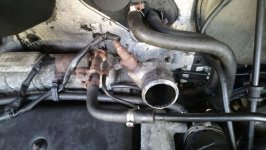
Ok, so in this photo I've marked the 3 fuel ines to the flame start with coloured lines.

Red - This comes from the flame start fuel solenoid, is this the fuel return to the tank?

Yellow - this comes from the hi pressure pump to the fuel solenoid, is this the 'supply' to the flame start?

Blue - This comes from the high pressure pump and appears to vent into the inlet manifold.

IMG_0183.jpeg
 
To me the blue marked one is a vacuum pipe maybe to the the turbo so nothing to do with the flame start device, I am assuming the yellow marked one is an electrical supply to the flame start device, the red marked one looks like an afterthought and nothing to do with it.
The pipe with a union nut at the flame device I am guessing is the fuel supply to the flame device and maybe from the injector return side.
@Communicator I believe has more detailed pdf etc. on the correct connections.
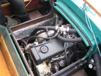
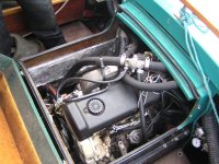
It may not help but this is one of those 2.8idt engines from a 1997 Ducato Maxi 3.5 tonne van, that I fitted in a boat, as I mentioned before the white wire was to be used for the flame start device , but I never had need of it as engine always burst into life at first touch of the key.:)
 

Attachments

  • PA290311.JPG
    PA290311.JPG
    711.1 KB · Views: 4
May I again suggest that @bugsymike is crediting me with more knowledge than I possess, but I will try to help.

The thermal starter requires, a high current electrical supply for the glowplug, and a second lower current supply for electromgnetic valve.
On engines with mechanically controlled injection, such as the 2.8idTD these supplies will need to be controlled via a special relay, similar to a glowplug controller.
As regards fuel supply I would expect it to be teed off the supply from the fuel lift pump in the tank. If a lift pump is not used, it may be possible to obtain a supply from the fuel return from the injection pump. Perhaps this alternative would need a control valve to maintain sufficient pressure?

I suggest that the blue marked pipe is a manifold pressure sensing connection for the Bosch EV pump, which allows the pump to increase the amount of fuel injected according to boost pressure. As I understand the 2.8idTD boost pressure is limited by a pressure capsule supplied directly from the turbo assembly.

The red marked pipe may, as suggested be fuel return pipe, with the rusty fitting on the end being the conjectured pressure maintaining valve?

I have borrowed the attached photo from the "Motor Roam" website. It shows a more complete installation.

That leaves the yellow pipe to be the supply as suggested.

Here is a link to the Motor Roam website, which @evildan may find helpful.
 

Attachments

  • 2.8idTD Flame Starter.jpg
    2.8idTD Flame Starter.jpg
    105.4 KB · Views: 4
Thanks @Communicator and @bugsymike

ok, so I've marked that photowith the same colours -

2.8idTD Flame Starter.jpg


I can see the yellow goes to the high pressure pump and looks like a return line ot me as its small, but it is T'd into the red pipe just before the flame start solenoid.

All I'm really asking is where does that red fuel line go off to? Is that the supply from the tank or a return to the tank?
I have another same diamete fuel line that goes directly to the high pressure fuel pumpand looks like it goes back to the vans fuel tank. (but I just have the engine out of the van!)
 
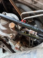
also these are the same pipes at the pump end (reuploaded with correct colours)
IMG_0185.jpeg


Green is what I'm assuning is the main fuel feed to the high pressure fuel pump.

IMG_0184.jpeg


IMG_0182.jpeg
 

Attachments

  • IMG_0185.jpeg
    IMG_0185.jpeg
    1,013.4 KB · Views: 7
Last edited:
These last pictures are a bit clearer, I am sorry if I am a bit vague, it was many years ago that I worked on them on Iveco Daily's and even the boat Fiat Ducato engine conversion was roughly 20 years ago and ran without the need of flame start connected.
Communicators guidance is much more relevant as I suspected.:)
I see the fuel solenoid has an arrow of fuel direction stamped on it. I am guessing the green marked pipe supplying the solenoid valve is the return from the injector pump as mounted high on the front of the pump to aid bleeding normally with flow inwards usually lower down.
The yellow marked pipe on the diaphragm housing on injector pump I believe is the vacuum control of the pump to raise pressure when turbo boost comes in as I think it is connected at the other end to the inlet manifold in one of your earlier photos. If that is the case then the pipe marked in yellow at the solenoid is not the same as that would carry fuel. In your first photo at #3 is it possible the colours are reversed?
What low pressure pumping supply is there on this vehicle as older ones had a mechanical lift pump by the injector pump, I believe later Ducatos had an electric pump in the tank , but Iveco Daily's had a electric pump on the chassis rail. If you can activate this it will help guide you as to what is fuel supply and what is vacuum.
The only flame start device I had need of and was able to repair when faulty, was On Perkins 4.108 diesel engines used in Mk Ford Transits and early Bedford CFs, slow but economical for their day.
They used a return from the injectors to keep a reservoir topped up with diesel so was ready to ignite before engine cranking and was a simply single wire connection to heat the element red hot at which point a thermal valve would open and the gravity fed diesel would then ignite so ready to crank engine, it worked very effectively.
 
I still need to figure out If green is fuel from the tank and red is the return to the tank?

Its a 2.8 idTd out of an unknown year (1999-2001) fiat ducato that I will be fitting to a 1992 fiat ducato chassis hymer. There is currently no lift pump or inline pump on my van (as far as I'm aware)

Yes the 1st photo in the 3rd post has the colours the wrong way - I've re labled them here -

IMG_0185.jpeg


also heres a couple more of the pump

IMG_0187.jpg
IMG_0188.jpg
 
As before

Blue is manifold pressure line to Bosch VE pump.

And subject to confirmation yellow is return line from Bosch VE pump, while green is return line to tank. It should be possible to confirm this by downloading a diagram of the Bosch VE pump.
 
ok, so if green is return, where does the engine get the fuel from? There are no other fuel lines/ inlets?
 
ok, so if green is return, where does the engine get the fuel from? There are no other fuel lines/ inlets?
So what then is braided hose connecting to injection pump at bottom of first photo in post #9? You should note that the leak off connection on the Bosch pump is radial at the drive end, probably on the underside. This appears to be extended by the shaper metal pipe with union that extends from under the pump.
 
Just had another look at my boat engine photo, on your green pipe at left side/top of injector pump I think that is the injector pump inlet as on my boat engine the pipe runs down from the left of photo towards where my fuel tank was situated. I didn't need a lift pump as tank close to injector pump so was able to draw through filter with no issues.It is the banjo pipe union and I can read on the then new rubber hose "oil" as in OK for fuel etc.
Also in general terms fuel feed pipe in, is usually larger than the return pipe.
 

Attachments

  • PA290311.JPG
    PA290311.JPG
    711.1 KB · Views: 3
Thanks @bugsymike
I agree thats the fuel inlet to the high pressure pump.
So what is the red pipe? The return after the flame start back to the fuel tank? Or a seperate feed to the flame start which would leave me with no return to the tank!
 
So what then is braided hose connecting to injection pump at bottom of first photo in post #9? You should note that the leak off connection on the Bosch pump is radial at the drive end, probably on the underside. This appears to be extended by the shaped metal pipe with union that extends from under the pump.
Apologies, I was misreading a diagram. That location at the drive end is for the pump inlet from tank. There is an internal leak off valvein that area, hence my confusion.

So with that correction we have the yellow marked line as the fuel inlet, which leaves the green marked line to be the fuel return. Colours refer to those used in post #9.

Thinking outside the box, I am aware that some earlier engines had lift pumps, and some did not, relying on the fuel transfer pump in the injection pump to draw fuel from the tank. I am wondering whether those engines with flame starters used a lift pump to supply both flame starter and injection pump, while engines with glowplugs used did not have a lift pump? Did existing engine use glowplugs?
 
Thanks @bugsymike
I agree thats the fuel inlet to the high pressure pump.
So what is the red pipe? The return after the flame start back to the fuel tank? Or a seperate feed to the flame start which would leave me with no return to the tank!
I am thinking the red is the return/leak off from the injectors and possibly coming from the injector pumps return also, so that it feeds the flame device but then continues back to the fuel tank as a single return pipe. On the old Perkins I referred to, the flame start device was fed from the return/leak off side of the injection system.
Re the original engine and if it had heater plugs, wouldn't that depend on if it was a Indirect Injection older type engine or not as maybe that was a 2.5 originally?
 
Back
Top