Technical Need help with 123 ignition

Currently reading:
Technical Need help with 123 ignition

Uaglio

New member
Joined
Oct 13, 2017
Messages
153
Points
43
Location
New York
So I’m putting a new 123 distributor on my rebuilt 126 650 engine and not sure of a few things.

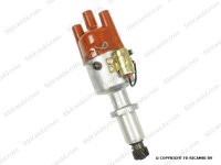
First off, looks like I got the full ignition and distributor kit; I thought I was getting one that was fully electronic with a dummy distributor cap, but looks like it’s a conventional cap and there’s a rotor inside. No points or condenser. The unit has only one black and one red wire that attach to the coil; no blue ground wire. Incidentally, the instructions are useless - they are for models without the cap and rotor (where timing is set with a set screw and flashing LED), and with a blue wire. They don’t apply to my model.

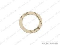
1. Spacer - the kit came with a spacer and new hold down clamp. I compared the rebuilt 126 engine’s conventional distributor to it and it looks like the 123 kit is meant to be used without the spacer (otherwise with the spacer it would be too short). I think the spacer is for using the same distributor on a 500 engine. I did notice that the distributor’s collar (where the hold down clamp touches down) has a notch in its edge that looks like it’s supposed to accommodate the hold down clamp bolt. It isn’t necessary for that and the cut out actually looks like it would allow a tiny open gap against the crankcase that might let oil out. I used the circular paper gasket from my rebuilt engine’s distributor and clamped it on, but it doesn’t seem right to me. Anyone know if this is normal?

2. How to set timing? Since this distributor has no electronic set screw for timing, is it just a matter of rotating it until the engine runs smoothly? Or using a timing light?

3. No blue wire - I’m assuming that is normal and the ground is coming from the negative (1) side of the coil, which is grounded.

Thoughts appreciated!
 
I agree that the kit is misleading as you only really lose the points, condenser and advance mechanisms. There should be instructions with it but they can be downloaded at the website.
The spacer is for use on a 499cc engine and I would use a gasket or a good quality sealant.
A blue wire is not needed.
Timing is by turning the body of the distributor as normal.
To set up, align the TDC mark on the oil spinner pulley with the arrow on the timing cover. By removing the rocker cover identify which cylinder is on the firing stroke by observing which one does not have any depressed rocker arms. Taking account of the fact that it is turned slightly as it's inserted, fit the 123 so that the rotor arm faces the direction that would give a spark to your firing cylinder and lightly secure with the clamp.
Connect the red wire only to the positive supply terminal of the coil. Turn on the ignition and you may see a tiny, green LED looking downwards onto the 123 with the cap removed. If not, slowly rotate the unit until that light is seen. Turn off ignition, secure the distributor, replace the cap, rotor, HT leads etc. Connect the black wire to the negative coil terminal and you're done. Ideally, once the engine runs and is warmed-up you need to set the timing to check that you are at maximum advance at high RPM, but that's a different novel I have written. ;)
 
Peter, that was super helpful. Thanks so much. I’m still not totally sure if I should be separately grounding the negative side of the coil, but I’ll figure it out. Thanks!
 
Peter, that was super helpful. Thanks so much. I’m still not totally sure if I should be separately grounding the negative side of the coil, but I’ll figure it out. Thanks!
You remove the LT lead from the negative of the coil which previously connected with the distributor post and that is replaced with the 123 black one.
The earthing/grounding of the electronics is said to be via the body of the unit through the engine block.
The manual suggests the if the original distributor is still fitted, the direction of the rotor-arm indicates exactly which way you should fit the new one.
They also suggest that if the LED is on you should turn clockwise until it's off and then anti until it just lights again.
I was very sceptical about the unit at first. After significant rosd-testing and careful adjustment I am now very pleased with it. :)
 
Last edited:
Thanks again for the help and tips. I’m still not totally sure why the new distributor has a notch cut out of the ring/flange where it seats against the block. You can see it in the photo on the right below. But as you can also see in the photos below, it looks like the 123 Ignition distributor has an oil seal O-ring on the shaft. The standard replacement R/126 distributor has no O-ring. I’m going to use the paper circular gasket and then keep an eye on it to make sure there are no leaks.
 

Attachments

  • E528B39C-D703-40DA-9F32-52E888B5B1BA.jpeg
    E528B39C-D703-40DA-9F32-52E888B5B1BA.jpeg
    31.6 KB · Views: 58
  • 36ED2160-8854-4573-9F2F-D9322297C8D8.jpeg
    36ED2160-8854-4573-9F2F-D9322297C8D8.jpeg
    38.1 KB · Views: 65
  • 91526A4D-465A-49DC-9959-284EA293BDCA.jpeg
    91526A4D-465A-49DC-9959-284EA293BDCA.jpeg
    25.5 KB · Views: 52
1. Spacer - the kit came with a spacer and new hold down clamp. I compared the rebuilt 126 engine’s conventional distributor to it and it looks like the 123 kit is meant to be used without the spacer (otherwise with the spacer it would be too short). I think the spacer is for using the same distributor on a 500 engine. I did notice that the distributor’s collar (where the hold down clamp touches down) has a notch in its edge that looks like it’s supposed to accommodate the hold down clamp bolt. It isn’t necessary for that and the cut out actually looks like it would allow a tiny open gap against the crankcase that might let oil out. I used the circular paper gasket from my rebuilt engine’s distributor and clamped it on, but it doesn’t seem right to me. Anyone know if this is normal?

I've fitted a few of these and two just recently... please always fit the spacer. I saw the remains of an engine where an engineer up North, had fitted the unit without the spacer. It meant that the bottom of the shaft of the 123 unit came into contact with the camshaft, this resulted in metal debris that munched the engine up really badly. In fact the crank case was not salvageable.
 
Hmm, appreciate the comment but pretty sure the 123 distributor, when used in a 650 engine from a 126, should go in without the spacer. I compared it to the size of a new conventional distributor and it’s the same size without the spacer. The spacer would effectively shorten the shaft. I think the spacer is for use when it is installed in a 500 engine, which uses a similar but slightly shorter distributor shaft. I also observed it from underneath after removing my oil pan and I could see the distributor gear seems to engage properly. I’ve been running it installed without the spacer and it runs fine. There’s an o ring on the shaft that prevents oil loss from the notch.
 
Last edited:
Hmm, appreciate the comment but pretty sure the 123 distributor, when used in a 650 engine from a 126, should go in without the spacer. I compared it to the size of a new conventional distributor and it’s the same size without the spacer. The spacer would effectively shorten the shaft. I think the spacer is for use when it is installed in a 500 engine, which uses a similar but slightly shorter distributor shaft. I also observed it from underneath after removing my oil pan and I could see the distributor gear seems to engage properly. I’ve been running it installed without the spacer and it runs fine. There’s an o ring on the shaft that prevents oil loss from the notch.

It might be worth, looking at the gear on the bottom and how it meshes with the cam inside the crank case.

It's always possible that Fiat did something different, but every 126 & 500 engine I've built (and I'm not sure how many I've built) have the spacer fitted with a 123 unit.

I've selected some pics where you should be able to see the spacer:

IMG_1406.jpg

IMG_1663.jpg

IMG_3291.jpg

IMG_4400.jpg

IMG_4414.jpg

IMG_4706.jpg

IMG_4783.jpg

IMG_4785.jpg

Does anyone know how to rotate the images?
 
Got to say I agree with the those saying a spacer is only needed on a 500cc engine with a 123.

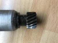
If you look at the picture (a bit out of focus) below this is a 126 distributor with points that was fitted in my 500cc engine for years without a spacer as it came like that when I bought the car. You can clearly see by the wear on the teeth that it wasn't meshing fully on camshaft because it was missing the spacer, it worked but it wasn’t correct.
 

Attachments

  • 2A6595E3-FED5-474D-9A89-DD7899CAC08C.jpeg
    2A6595E3-FED5-474D-9A89-DD7899CAC08C.jpeg
    2.4 MB · Views: 53
I sent a note to Ron at Albertronics (who make the 123 unit) he says as follows:

The best way, is to compare your old ignition with the 123ignition. From that point you mount the ring or not.


Perhaps not as definitive as we'd like. Point is that I would physically measure (and accurately) from the top of the opening for the distributor on the outer casing to the highest point of the gear on the camshaft and compare between the 126 and the 500 units. Might be worth asking any members with stripped down engines to do the same (unfortunately both my engines are fully assembled) and I've gotten rid of most of the surplus parts I had.

I thought I had done this some years ago and come to a conclusion.
 
Last edited:
I think picture from the other thread clearly indicates which one needs a spacer and which doesn’t.

Top is a 126 distributor
Bottom is a 500 distributor
 

Attachments

  • C529E86B-6556-4D3D-9A72-FD163AF54DA0.jpeg
    C529E86B-6556-4D3D-9A72-FD163AF54DA0.jpeg
    382.1 KB · Views: 47
That's really confused me... I was looking for the picture showing the damage to the 123 unit - it was definitely on a 650cc engine. The guy who owned it lived near Mansfield and I know the car quite well. I wonder is the Polski crank case and Italian 650 crank cases are the same casting?

I'll keep looking for the pics showing damaged unit. I'll also look pull the 123 units out after running a while, once the 595 & 650 engines have been commissioned.

For what it's worth, I have a Polish-made (FSM) 126 engine. I think the basic engine casting and construction is the same as the Italian made 650s. My 123 distributor (and I use the full model; the one that comes with a mechanical rotor and distributor cap) definitely meshes properly with the cam gear, so I know it is right. I still don't understand why they have that cut-out notch in the flange at the top of the distributor shaft where it mates to the block, but that's a different issue. (I think it's probably to allow clearance for a clamp bolt for some versions of the same distributor body. Here, it looks like the notch is acceptable because there is an oil sealing o-ring on the shaft.)

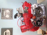
Incidentally, it looks like one of your engines (the red one) doesn't have a spacer. The spacer is pretty thick - maybe 7 mm by memory? It's not just a thin flat washer/gasket thing. It's designed to take up space to shorten the distributor gear shaft. I think if you used the spacer on a 126 engine (as opposed to a true 500cc engine), your distributor gear wouldn't reach far enough to engage with the cam gear. So you'd have the opposite problem - no damage to the gears, but your distributor would not be turned by the cam gear. Not likely the engine would run at all in that state. By contrast, mounting the 126 distributor in a 500cc engine with no spacer makes the shaft slightly too long; while it engages the cam gear, it's too far below the gear and doesn't mesh properly and will wear out over time (see photo in Vitesse's post above). Maybe it's this latter state you recall seeing in an engine autopsy.
 
Last edited:
The only reason I can think of for that cut out is so you can get a screwdriver cleanly on the screw on the base of the distributor body if you need to take it apart?
 
Incidentally, it looks like one of your engines (the red one) doesn't have a spacer. The spacer is pretty thick - maybe 7 mm by memory? It's not just a thin flat washer/gasket thing. It's designed to take up space to shorten the distributor gear shaft. I think if you used the spacer on a 126 engine (as opposed to a true 500cc engine), your distributor gear wouldn't reach far enough to engage with the cam gear. So you'd have the opposite problem - no damage to the gears, but your distributor would not be turned by the cam gear. Not likely the engine would run at all in that state. By contrast, mounting the 126 distributor in a 500cc engine with no spacer makes the shaft slightly too long; while it engages the cam gear, it's too far below the gear and doesn't mesh properly and will wear out over time (see photo in Vitesse's post above). Maybe it's this latter state you recall seeing in an engine autopsy.

There's something else going on here that I need to get to the bottom of. I checked my 595 which is in the car I'm working on at the moment and with the spacer in and the distie top off, when the engine is turned over the rotor spins as it should. The pic showing the shaft of the distributor on the gear of the cam is from this engine and there's no question that it's engaged.

All of the other engines that I can find pics (as above) definitely have a spacer and all ran well (including the red one which was set up at RGS Motorsport on the dyno) - here's a link where you can zoom in and see the detail - (to view other pics go to album copy & paste https://beta.photobucket.com/u/nathanrobo/a/171aaad3-fb47-4bb9-bdf5-a9f99ef0a572)


I'm always happy to be wrong (it means I've learnt something), but there's something different going on here.
 
Last edited:
The only reason I can think of for that cut out is so you can get a screwdriver cleanly on the screw on the base of the distributor body if you need to take it apart?
The reason for the notch is so you can get a regular-sized hex wrench in there to adjust the timing curves. If you notice, the hex plug that gives you access to the timing curve adjustment "screw" is in line with the notch. I have adjusted my timing curve, and you wouldn't be able to unscrew the plug with a standard 90 degree hex wrench otherwise.
 
Back
Top