Hi All, I have a very weird ABS problem with my Schumi that I would appreciate some advice on. After rebuilding all 4 corners of the car and replacing all ABS sensors with new items, I was very dismayed to see that the ABS warning light was still on. I hooked up an OBDII reader and got the following error:


The system is freely streaming data and live-updates the brake pedal status (not sure what the 1.75 km/h offset is about on all 4 wheels, the car was stationary).
I decided to also use FiatECUScan, which returned the following:

After some research, I found a Polish site which mentioned this error, so I put it through Google Translate:

I decided to get the cluster PCB out of the car so that I could test all diodes, including the light-emitting variety - using the diode test on my multimeter, everything seemed to check out.
The next port of call was to check out the signals getting to the cluster, so I referred to the technical manual for the ABS and cluster circuits.

The ABS circuit seems to feature a different representation of the cluster "E50", with 3 interface connections; my unit (part# 735290647) only has two. I used the wire colours and symbols to reconcile the correct connections.
I also decided to map pertinent tracks on the actual PCB and count the pins/parts and to work out which connector is which (note the colours I chose are just for high contrast - this is not the wiring colours):

Pin 4 of connector B is what I expect the ABS controller good/no good signal to arrive on. To give me some idea of what to expect, I probed Pin B10, the airbag good/no good signal (in which the warning circuit looks identical), I found that the voltage level started at ~3.5 V when the ignition key was initially turned, then rose to 12 V when the light went out. The ABS pin comes on at 3.5V and stays there.
I also decided to map the pins to colours, which I include here in the event it helps someone at some point in time, although there are a couple of omissions:

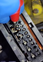
I then thought it logical to turn my attention to the signal source, at the ABS modulator, so I found these references and took some photos:

The ABS connector removed, everything looks pretty clean on the controller.
...and the connector side:

Here's where things get weird - with the connector off the ABS controller and the instrument cluster unplugged, pin 20 (verified pink wire) of the ABS connector is not only NOT connected to pin 4 of cluster A4, it has a 0 ohm short to earth. ABS connector pin 21 is also shorted to earth, neither or which I would expect.


Looking at how the signals route through the car, I followed the ABS loom from the ABS controller, but quickly found that it tightly tucks up under the bulkhead shelf and it is difficult to follow. I am looking for connection D5, which, from the ABS wiring diagram, seems to facilitate connection from the ABS look into the cabin. Does anyone know where this is?
If you're still reading and have not been put to sleep, thank you for your time! Any advice on what to look at next would be very much appreciated and if there are other tests I may perform/identification of things I may have got wrong so far.
The system is freely streaming data and live-updates the brake pedal status (not sure what the 1.75 km/h offset is about on all 4 wheels, the car was stationary).
I decided to also use FiatECUScan, which returned the following:
After some research, I found a Polish site which mentioned this error, so I put it through Google Translate:
I decided to get the cluster PCB out of the car so that I could test all diodes, including the light-emitting variety - using the diode test on my multimeter, everything seemed to check out.
The next port of call was to check out the signals getting to the cluster, so I referred to the technical manual for the ABS and cluster circuits.
The ABS circuit seems to feature a different representation of the cluster "E50", with 3 interface connections; my unit (part# 735290647) only has two. I used the wire colours and symbols to reconcile the correct connections.
I also decided to map pertinent tracks on the actual PCB and count the pins/parts and to work out which connector is which (note the colours I chose are just for high contrast - this is not the wiring colours):
Pin 4 of connector B is what I expect the ABS controller good/no good signal to arrive on. To give me some idea of what to expect, I probed Pin B10, the airbag good/no good signal (in which the warning circuit looks identical), I found that the voltage level started at ~3.5 V when the ignition key was initially turned, then rose to 12 V when the light went out. The ABS pin comes on at 3.5V and stays there.
I also decided to map the pins to colours, which I include here in the event it helps someone at some point in time, although there are a couple of omissions:
I then thought it logical to turn my attention to the signal source, at the ABS modulator, so I found these references and took some photos:
The ABS connector removed, everything looks pretty clean on the controller.
...and the connector side:
Here's where things get weird - with the connector off the ABS controller and the instrument cluster unplugged, pin 20 (verified pink wire) of the ABS connector is not only NOT connected to pin 4 of cluster A4, it has a 0 ohm short to earth. ABS connector pin 21 is also shorted to earth, neither or which I would expect.
Looking at how the signals route through the car, I followed the ABS loom from the ABS controller, but quickly found that it tightly tucks up under the bulkhead shelf and it is difficult to follow. I am looking for connection D5, which, from the ABS wiring diagram, seems to facilitate connection from the ABS look into the cabin. Does anyone know where this is?
If you're still reading and have not been put to sleep, thank you for your time! Any advice on what to look at next would be very much appreciated and if there are other tests I may perform/identification of things I may have got wrong so far.