Technical Ducato heater resister

Currently reading:
Technical Ducato heater resister

Gazzaman

New member
Joined
Feb 6, 2025
Messages
5
Points
1
Location
Liverpool
Having problems on 2011 ducato
The heater stopped working, worked on a few positions but not all , then stopped altogether .
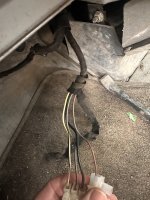
Now from reading up on here I’ve seen it’s the heater resistor , which I’ve purchased a new one, but the new harness has five wires where the old one had 4 and all the colours on the new one are totally different to the old one and I can’t match them up as the old harness had melted and wires were disconnected
Does anyone know which wire goes to which
I seen circuit diagrams on the internet, but there no use to me I need actual colour to colour if anyone could help
The sequence on the new harness is right to left
Black blue red green yellow
Thanks
 
Here's a post with the EUR 5 (post 2011) diagram:


And the x250 wire colour coding here in the download section of the forum.
 
As stated the resistor has only 4 connections, but the connector has 5.

If you look closely at the resistor, you will see that at one end it connects to two pins, mate the connector and resistor, and I suspect the you will find that the black and blue wires are commoned together at that end of the resistor. The black wire is for an earth connection, which may not be required. The blue wire will be for speed 4, red = speed 3, green = speed 2, and yellow = speed 1, with the whole resistor pack in service.

You should be able to identify the matching wires coming from the switch, by testing for for 12V coming through the motor, with ignition on. Take care. Alternatively test for continuity from the negative side of the motor connector.
 

Attachments

  • IMG_3352.jpeg
    IMG_3352.jpeg
    1.6 MB · Views: 23
These are the existing wire but need to Mack them up the the new colurs
With ignition on, and fan on speed 1, you should find 12V on only one wire, with either multimeter, or test lamp. Make note, and repeat for speed 2 etc.
 
Back
Top