Firstly make sure that you have the correct replacement wiring loom. There are two different versions - one for cars without air-conditioning and one for cars that have it. The looms that Fiat supply now have been modified so that the problem should never happen again.
The main tools you will need are radio 'keys', a flat-bladed screwdriver, an inspection torch, a 10mm socket, T25 and T27 torx bits and a flexible torx driver. You may be able to get away with a little less dismantling that I did but the whole job is awkward and the more wiggle room you can create the easier it gets. I've 'borrowed' a couple of photos from other excellent guides on this forum - I do hope their authors don't mind.
Under the glove-box in the passenger foot-well you'll find the bit in the picture. Remove the torx indicated in the picture.
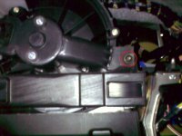
Then pull out the piece of plastic that it was holding in place. This picture shows the piece you should remove.
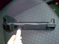
Remove the left (passenger) side of the 'transmission tunnel' by levering out the clips shown using a flat bladed screwdriver. I also removed the nut shown in the picture as this gives usefull extra wiggle room.
View attachment 131673
Remove the right (driver) side of the 'transmission tunnel' - first remove the nut shown and then lever out the clips the same as on the passenger side using a flat bladed screwdriver.
View attachment 131674
Push radio 'keys' into their holes and then using them to wiggle and gently pull the radio draw it out. Then pull off the aerial lead and remove the wiring block so that the radio can be removed completely.
View attachment 131675
View attachment 131676
Remove the four torx that hold in the radio cage (two are shown in the picture) and then remove the metal radio cage completely.
View attachment 131677
Remove the small panel immediately above the little nick-nack area at the from of the centre console by levering the front edge down with a flat-bladed screwdriver.
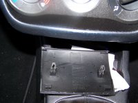
Where the panel was, at the very front edge there are two torx. They are difficult to spot but they are there. Remove them. The one on the left is fairly easy but the one on the right will require a flexible driver.
View attachment 131679
View attachment 131680
Completely remove the black plastic front of the heater controls complete with the knobs. This is done by very gently levering up the very delicate clips you can see on the top edge (there are only two in the photo as mine has one broken off) and then pulling the top forward which will free it from clips at the bottom.
View attachment 131681
Familiarise yourself with all the blocks on the new wiring loom. They are all different. You need to work out for each one which bit needs to be squashed or levered so that you know how to remove the old ones.
In the passenger foot-well there are three blocks that need to be disconnected. One is very high up and you will need to be on your back with you head as far into the foot-well as possible up against the bulkhead.
The two shown in this picture are to the fan itself (left) and the resister (right).
View attachment 131682
This one is tricky to get to - it activates a flap when the recirculation button is pressed. You can't really see it in this picture but just follow the lead up and you'll find it.
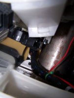
Tie a long length of sturdy string to one of the connectors you've just unplugged and then tape all three together, neatly so they take up as little room as possible.
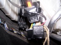
Having identified the cable from the back of the heater controls, down and out by the pedals and then up. With your head under the pedals, staring straight up you need to pull the wiring loom through from the passenger side. Ideally you need someone to help you with this although I managed it on my own. You need to help the taped together connectors to go up and over the highest point you can see under the passenger foot-well whilst pulling from as high as you can reach under the driver's foot-well.
Once through, remove the piece of string and tie it to the same connector on the new wiring loom. Then like before tape up the three connectors on the new wiring loom. As before but in reverse thread the new wiring loom through as high as you can reach under the driver's foot-well whilst pulling the string from as high as you can reach under the passenger foot well.
Once through, remove the tape and the string and connect the three brand new connectors to the fan, the resister and the re-circulation control.
Then back in the driver's foot-well undo the nut shown to remove the earth strap of the old loom and connect the earth strap of the new loom in its place.
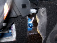
Pull the old wiring loom out of the hole where the radio was and disconnect the black connector and the blue connector. The blue connector requires you to squash down a small piece of plastic that then allows the black frame to turn through 90 degrees. Look at the new one to work out what I mean.
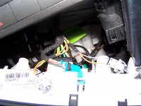
To remove the two bulb holders on the old loom remove the tiny screw shown in the centre of the picture to remove the clear plastic. You can then force a screwdriver down the side to pop them out. I've read someone claim that you can do this from the back without removing all the front of the heater controls but there's no way I could get that work.
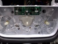
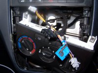
Follow the last piece of the old loom down to the final connector. You can get at it from the left side of the 'transmission tunnel'. Slide the block towards you off its mounting point. The blue piece of plastic then pulls up and this enables the two connectors to be pulled apart. I couldn't find a way to extricate this final connector so I cut it off with a pair of pliers. Luckily the new loom can be routed a slighly different way. Having cut this connector off, the old loom it should now be completly out and heading for the bin.
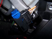
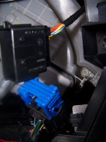
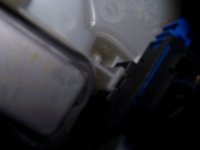
You should now be able to bring the new loom up from the driver's foot-well into the radio area to connect the black and blue connectors to the back of the heater controls and push in the two bulb holders. The final connector can be threaded down and out the bottom and can be put together from the passenger side foot well - just the reverse of disconnecting the old one.
Now put everything back together ..............
The main tools you will need are radio 'keys', a flat-bladed screwdriver, an inspection torch, a 10mm socket, T25 and T27 torx bits and a flexible torx driver. You may be able to get away with a little less dismantling that I did but the whole job is awkward and the more wiggle room you can create the easier it gets. I've 'borrowed' a couple of photos from other excellent guides on this forum - I do hope their authors don't mind.
Under the glove-box in the passenger foot-well you'll find the bit in the picture. Remove the torx indicated in the picture.

Then pull out the piece of plastic that it was holding in place. This picture shows the piece you should remove.

Remove the left (passenger) side of the 'transmission tunnel' by levering out the clips shown using a flat bladed screwdriver. I also removed the nut shown in the picture as this gives usefull extra wiggle room.
View attachment 131673
Remove the right (driver) side of the 'transmission tunnel' - first remove the nut shown and then lever out the clips the same as on the passenger side using a flat bladed screwdriver.
View attachment 131674
Push radio 'keys' into their holes and then using them to wiggle and gently pull the radio draw it out. Then pull off the aerial lead and remove the wiring block so that the radio can be removed completely.
View attachment 131675
View attachment 131676
Remove the four torx that hold in the radio cage (two are shown in the picture) and then remove the metal radio cage completely.
View attachment 131677
Remove the small panel immediately above the little nick-nack area at the from of the centre console by levering the front edge down with a flat-bladed screwdriver.

Where the panel was, at the very front edge there are two torx. They are difficult to spot but they are there. Remove them. The one on the left is fairly easy but the one on the right will require a flexible driver.
View attachment 131679
View attachment 131680
Completely remove the black plastic front of the heater controls complete with the knobs. This is done by very gently levering up the very delicate clips you can see on the top edge (there are only two in the photo as mine has one broken off) and then pulling the top forward which will free it from clips at the bottom.
View attachment 131681
Familiarise yourself with all the blocks on the new wiring loom. They are all different. You need to work out for each one which bit needs to be squashed or levered so that you know how to remove the old ones.
In the passenger foot-well there are three blocks that need to be disconnected. One is very high up and you will need to be on your back with you head as far into the foot-well as possible up against the bulkhead.
The two shown in this picture are to the fan itself (left) and the resister (right).
View attachment 131682
This one is tricky to get to - it activates a flap when the recirculation button is pressed. You can't really see it in this picture but just follow the lead up and you'll find it.

Tie a long length of sturdy string to one of the connectors you've just unplugged and then tape all three together, neatly so they take up as little room as possible.

Having identified the cable from the back of the heater controls, down and out by the pedals and then up. With your head under the pedals, staring straight up you need to pull the wiring loom through from the passenger side. Ideally you need someone to help you with this although I managed it on my own. You need to help the taped together connectors to go up and over the highest point you can see under the passenger foot-well whilst pulling from as high as you can reach under the driver's foot-well.
Once through, remove the piece of string and tie it to the same connector on the new wiring loom. Then like before tape up the three connectors on the new wiring loom. As before but in reverse thread the new wiring loom through as high as you can reach under the driver's foot-well whilst pulling the string from as high as you can reach under the passenger foot well.
Once through, remove the tape and the string and connect the three brand new connectors to the fan, the resister and the re-circulation control.
Then back in the driver's foot-well undo the nut shown to remove the earth strap of the old loom and connect the earth strap of the new loom in its place.

Pull the old wiring loom out of the hole where the radio was and disconnect the black connector and the blue connector. The blue connector requires you to squash down a small piece of plastic that then allows the black frame to turn through 90 degrees. Look at the new one to work out what I mean.

To remove the two bulb holders on the old loom remove the tiny screw shown in the centre of the picture to remove the clear plastic. You can then force a screwdriver down the side to pop them out. I've read someone claim that you can do this from the back without removing all the front of the heater controls but there's no way I could get that work.


Follow the last piece of the old loom down to the final connector. You can get at it from the left side of the 'transmission tunnel'. Slide the block towards you off its mounting point. The blue piece of plastic then pulls up and this enables the two connectors to be pulled apart. I couldn't find a way to extricate this final connector so I cut it off with a pair of pliers. Luckily the new loom can be routed a slighly different way. Having cut this connector off, the old loom it should now be completly out and heading for the bin.


You should now be able to bring the new loom up from the driver's foot-well into the radio area to connect the black and blue connectors to the back of the heater controls and push in the two bulb holders. The final connector can be threaded down and out the bottom and can be put together from the passenger side foot well - just the reverse of disconnecting the old one.
Now put everything back together ..............

