Static timing requires a little inventiveness, instead of watching for a spark you need to create a temporary circuit with a low wattage bulb between the coil -ve and ground or use a voltmeter to measure the PD across the same.
When the bulb is lit or the voltmeter reads 12v the circuit is open and you would be triggering a spark.
With this in mind you can basically follow the normal static timing setup: (taken from the lumenition fitting guide)
Turn engine and align timing marks making sure the rotor tip is pointing to the HT pick-up segment in the distributor cap of the recommended firing plug, normally No 1. With distributor cap removed the leading edge of the chopper blade should be 2/3rds across the lensed units in the direction of rotation.
Slacken distributor clamp bolt and very slightly turn distributor in direction of rotor rotation. This is just enough to bring the chopper blade before the point of passing between the lensed units. Switch on ignition taking care not to crank the engine. Very gently return the distributor against the direction of rotation to the exact point that the voltmeter reads around 12V or the test bulb lights. If you overshoot return far enough to start again otherwise you will time on backlash.
Just remember that the X1/9 times from cylinder #4 not cylinder #1. The correct timing marks are on the back of the timing belt cover (the metal plate) and cam pulley. The best place for timing the crank is from the flywheel but failing that the pulley wheel does have a decent timing mark on it.
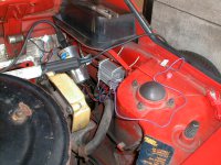
As for the green wire - I thought that was for the old condensor which you no longer have a need for. There certainly isn't anything I remember in the lumenition kit that relates to a green wire.
From memory you have a bundle of three wires to/from the distributor and the PDA50 module. You also have three wires to/from the module for power (red), earth (black) and coil -ve (brown). Everything else should be redundant.