DPF REGEN INDICATOR
This one is for the Tech-heads. I know some of you will be keenly interested in this, so a big hello to the four of you! For everyone else, if you feel your eyes beginning to glaze over – well, there is no shame...
For me, one of the bugbears of the Ducato is the lack of any indication that a DPF REGEN is underway. Knowing that information would enable the vehicle to be driven in the most suitable manner to ensure an efficient, complete and uninterrupted regeneration cycle. Apart from that, at the very least I would know it was occurring.
The cost of a DPF replacement, and/or a forced regen is, for me, the main thing to try and avoid. Just a simple indicator would suffice.
So, with multimeter, scan tool and calculator in hand the following circuit was designed, built and successfully tested.
But first, a note of warning. This is not an instructional “how to”, but a “how I did it”.
If you decide to attempt what I am describing, then you do so at your own risk and the responsibility of any issues arising belongs wholly with you and not me.
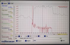
First, I had to measure the characteristics of the NTC DPF temperature sensor. This was done under actual operating conditions and recorded with my AUTEL scan tool. From the measurements it was apparent that the ECM has a 1k pull up resistor to a +5V rail and from that the impedance of the sensor could also be calculated across the range. The resultant Temperature/Voltage response curve is of the DPF temperature sensor in my 2018 Euro 6B,150HP, 2,3L Ducato.
During normal operating conditions on the open highway the DPF temperature could reach a maximum of 510 C passively (not in regen mode), so the design trigger point must be above that. Considering the curve is very flat at high temperatures and the change in signal is very small, I chose 530 C (0.544V) as the trigger point, which provides enough safety margin to be a reliable indicator of the DPF regen which is more than 600 C (approx. 650 C max).
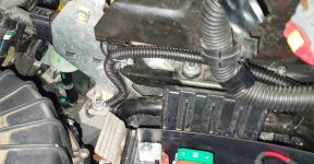
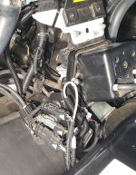
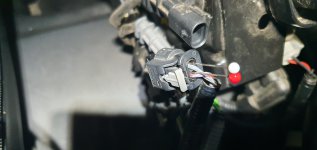
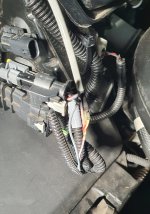
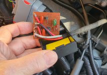
The photographs show the mounting location of the circuit, 12V supply point, earth and signal pickup, and the LED indicator. Due to the small signal variation, the earth point was critical and was chosen as near to the ECM reference as conveniently possible. To avoid an earth loop and introducing any signal errors only the “hot” side of the temperature sensor was connected to the indicator circuit, the earth already referenced by the prior earth point at the ECM. To safeguard against any possible induced signals, a shielded cable was used for the signal pickup, with the outer braid earthed at the indicator circuit board only. A single wire fed through the firewall to drive the LED inside the cabin, the earth for the LED picked up from inside the cabin, again to avoid any introduced voltage drop on the sensor earth circuit. The +12V supply point provided by inserting a fuse tap at F15 in the under-bonnet fuse location point. This fuse is the designated supply for the 12V dashboard outlet (Cig-Lighter socket).
For the initial test, I placed a temporary 18k resistor in parallel with the designed 18k resistor, which produced a switching point at around 390 C so the correct operation of the circuit could be observed during normal open highway driving.
After that, the circuit as designed was then tested under normal road conditions with a scan tool connected to confirm the LED illuminated at the beginning of a normal DPF REGEN and stayed on for the complete REGEN cycle. All worked as planned, and no interference observed to the existing FIAT system. A post-test scan for any vehicle faults proved negative.
The circuit is very simple, employing a LM358 op-amp configured as an open loop comparator and LED driver. The 78L05 provides the +5v regulated supply. The 10mm LED has a nominal brightness of 270mcd at 20mA and is driven with 12 mA in this circuit, providing ample brightness without glare. The Jaycar part number for the LED is ZD0203.
Further photographs show extra details and information.
This one is for the Tech-heads. I know some of you will be keenly interested in this, so a big hello to the four of you!
For me, one of the bugbears of the Ducato is the lack of any indication that a DPF REGEN is underway. Knowing that information would enable the vehicle to be driven in the most suitable manner to ensure an efficient, complete and uninterrupted regeneration cycle. Apart from that, at the very least I would know it was occurring.
The cost of a DPF replacement, and/or a forced regen is, for me, the main thing to try and avoid. Just a simple indicator would suffice.
So, with multimeter, scan tool and calculator in hand the following circuit was designed, built and successfully tested.
But first, a note of warning. This is not an instructional “how to”, but a “how I did it”.
If you decide to attempt what I am describing, then you do so at your own risk and the responsibility of any issues arising belongs wholly with you and not me.
First, I had to measure the characteristics of the NTC DPF temperature sensor. This was done under actual operating conditions and recorded with my AUTEL scan tool. From the measurements it was apparent that the ECM has a 1k pull up resistor to a +5V rail and from that the impedance of the sensor could also be calculated across the range. The resultant Temperature/Voltage response curve is of the DPF temperature sensor in my 2018 Euro 6B,150HP, 2,3L Ducato.
During normal operating conditions on the open highway the DPF temperature could reach a maximum of 510 C passively (not in regen mode), so the design trigger point must be above that. Considering the curve is very flat at high temperatures and the change in signal is very small, I chose 530 C (0.544V) as the trigger point, which provides enough safety margin to be a reliable indicator of the DPF regen which is more than 600 C (approx. 650 C max).
The photographs show the mounting location of the circuit, 12V supply point, earth and signal pickup, and the LED indicator. Due to the small signal variation, the earth point was critical and was chosen as near to the ECM reference as conveniently possible. To avoid an earth loop and introducing any signal errors only the “hot” side of the temperature sensor was connected to the indicator circuit, the earth already referenced by the prior earth point at the ECM. To safeguard against any possible induced signals, a shielded cable was used for the signal pickup, with the outer braid earthed at the indicator circuit board only. A single wire fed through the firewall to drive the LED inside the cabin, the earth for the LED picked up from inside the cabin, again to avoid any introduced voltage drop on the sensor earth circuit. The +12V supply point provided by inserting a fuse tap at F15 in the under-bonnet fuse location point. This fuse is the designated supply for the 12V dashboard outlet (Cig-Lighter socket).
For the initial test, I placed a temporary 18k resistor in parallel with the designed 18k resistor, which produced a switching point at around 390 C so the correct operation of the circuit could be observed during normal open highway driving.
After that, the circuit as designed was then tested under normal road conditions with a scan tool connected to confirm the LED illuminated at the beginning of a normal DPF REGEN and stayed on for the complete REGEN cycle. All worked as planned, and no interference observed to the existing FIAT system. A post-test scan for any vehicle faults proved negative.
The circuit is very simple, employing a LM358 op-amp configured as an open loop comparator and LED driver. The 78L05 provides the +5v regulated supply. The 10mm LED has a nominal brightness of 270mcd at 20mA and is driven with 12 mA in this circuit, providing ample brightness without glare. The Jaycar part number for the LED is ZD0203.
Further photographs show extra details and information.
Attachments
-
 1 Schematic.jpg938.1 KB · Views: 401
 -
 2 PCB.jpg1.2 MB · Views: 180
 -
 3 Curve.jpg700.2 KB · Views: 169
 -
 4 Location.jpg1.5 MB · Views: 397
 -
 5 Supply Point.jpg903.4 KB · Views: 174
 -
 6 Earth Point.jpg1.7 MB · Views: 627
 -
 7 Signal Pickup.jpg688.4 KB · Views: 178
 -
 8 LED Off.jpg1.3 MB · Views: 679
 -
 9 LED On.jpg1.3 MB · Views: 190
 -
 10 Graph.jpg1.8 MB · Views: 393
 -
 11 Back Probe.jpg1.9 MB · Views: 430
 -
 12 Sensors.jpg2.7 MB · Views: 327
 -
 13 Signal Tap.jpg1.4 MB · Views: 177
 -
 14 Circuit1.jpg948.6 KB · Views: 163
 -
 15 Circuit2.jpg1 MB · Views: 183


